
Injection Molding Design Guidelines for Optimal Results
What Injection Molding Design Guidelines Mean for Optimal Results
Injection molding design guidelines are the practical rules engineers use to design plastic parts that fill completely, cool evenly, eject cleanly, meet tolerance targets, and stay cost-effective in production. In simple terms, good design guidelines help a manufacturer or supplier turn a 3D model into a stable molded part with fewer defects, lower tooling risk, and more predictable unit pricing.
When engineers ask for injection molding design guidelines, they are usually trying to solve five production problems at once: sink, warp, short shots, cosmetic defects, and unnecessary tooling cost. The part may look fine on CAD, but if wall thickness varies too much, draft is missing, ribs are oversized, or the gate location is poorly planned, the mold will be harder to build and the production result will be less reliable.
At a practical level, strong design guidelines should help you:
- maintain uniform wall thickness and stable shrink behavior
- reduce sink marks, warpage, weld lines, and trapped gas
- protect cosmetic surfaces and sealing faces
- improve cycle time and cavity efficiency
- balance part performance with tooling and unit cost
The most important point is this: injection molding success is decided early. Once the mold steel is cut, design changes become slower and more expensive. That is why experienced product teams review geometry, resin, parting line, ejection, finish, and tolerance strategy before tooling release rather than after the first sampling round.
Why Injection Molding Design Guidelines Matter in a Faster, More Cost-Driven Manufacturing Market
Injection molding design guidelines matter more today because product development cycles are shorter, parts are more complex, and procurement teams are under pressure to reduce both launch risk and landed cost. In medical devices, automotive electronics, smart home products, and industrial equipment, buyers want parts that are lighter, smaller, more attractive, and easier to assemble. That puts more pressure on the molded component and less tolerance for design mistakes.
The market is also changing in how parts are sourced. Many OEMs no longer separate prototype work, tooling, molding, finishing, assembly, and export logistics into different suppliers if they can avoid it. They prefer manufacturing partners who can review the part early, recommend DFM changes, build the tool quickly, and support production scale-up without resetting the project. That is one reason manufacturers like TEAM Rapid have become more relevant to international buyers. With customers in more than 25 countries, 500+ satisfied customers, and 6,000+ delivered projects, TEAM Rapid reflects a broader shift toward integrated, engineering-led sourcing.
Another reason these guidelines matter is miniaturization. A small snap feature, thin-wall housing, insert-molded terminal carrier, or clear optical cover has much less room for process variation than a larger commodity part. Seemingly minor design decisions can change resin flow, cooling balance, ejection force, and final appearance.
For sourcing teams, injection molding design guidelines are not just an engineering checklist. They directly affect:
- tooling complexity and steel choice
- cavity count and cycle time
- inspection burden and rejection rate
- packaging and assembly efficiency
- time to first article approval
TEAM Rapid, for example, is often used as a benchmark because it combines rapid manufacturing support with detailed manufacturability analysis. In real projects, that means reviewing design risks before tooling, identifying where resin consumption can be reduced, and finding ways to maximize mold cavities or improve cycle time without sacrificing part function. Those are exactly the issues shaping the market today: faster launches, better part performance, and tighter cost control.
Core Injection Molding Design Guidelines for Wall Thickness, Draft, Radii, Materials, and Tolerances
Injection molding design guidelines start with geometry and material behavior. If the part is dimensionally stable, easy to fill, and easy to eject, the rest of the production process becomes much more predictable. If not, even a high-quality mold shop will spend more time compensating for design issues that should have been corrected in DFM.
Geometry rules that prevent common molding defects
The most useful guideline is uniform wall thickness. Large thickness jumps create uneven cooling, which drives sink and warp. Draft is the second rule. Any face parallel to tool pull should have enough draft to release cleanly without drag marks or part distortion. After that come corner radii, rib sizing, boss support, and parting-line placement.
| Design Feature | Practical Guideline | Why It Matters |
|---|---|---|
| Nominal wall thickness | Keep walls as uniform as possible; many molded parts work well in the 1.0-3.0 mm range, while small precision parts often run 0.8-2.0 mm | Improves fill, cooling, and dimensional stability |
| Draft angle | 0.5° minimum on polished faces, 1°-2° preferred for general features, more for textured surfaces | Reduces scuffing, drag, and ejection force |
| Inside corner radius | At least 0.5 x wall thickness; 0.75 x wall thickness is often better | Improves flow and reduces stress concentration |
| Rib thickness | About 50%-60% of the adjoining wall | Helps stiffness without creating sink |
| Rib height | Often kept near 2.5-3.0 x wall thickness unless analysis supports more | Controls fill risk and cosmetic read-through |
| Boss design | Support tall bosses with gussets and good base radii | Prevents cracking, sink, and deflection |
| Molded tolerance | (\pm 0.05) mm is a realistic standard target for many precision molded features | Aligns design expectations with process capability |
A second design rule is to place cosmetic and functional features intentionally. Keep gates away from optical faces, visible exterior surfaces, and critical seal areas whenever possible. Keep ejector pins off display surfaces and avoid putting parting lines across sealing diameters, snap faces, or threaded engagement zones.
Material and finish choices within injection molding design guidelines
Material selection is just as important as geometry. Different plastics shrink differently, flow differently, and respond differently to wall variation or molded-in stress. Suppliers with strong Injection Molding capability typically review resin choice at the same time as part geometry.
TEAM Rapid, for example, supports ABS, PC, PP, PA/Nylon, POM, PEEK, TPU, TPE, Silicone, and more, which covers most common structural, cosmetic, chemical-resistant, flexible, and high-performance needs in production programs.
| Material / Finish Area | Best Use in Design | Design Note |
|---|---|---|
| ABS | General housings, consumer parts, painted parts | Good balance of cost, stability, and finishability |
| PC | Clear or impact-resistant parts | Needs careful gate and polish strategy for optics |
| PP | Utility parts, living hinges, cost-sensitive programs | Shrink and flex behavior should be designed in early |
| PA/Nylon | Mechanical and connector parts | Moisture and tolerance strategy matter |
| POM | Low-friction components, latches, gears | Excellent for wear but needs correct shutoff and tolerance planning |
| PEEK | High-temperature or demanding technical parts | Higher resin cost; DFM discipline becomes critical |
| SPI polish | Cosmetic or optical faces | Lower Ra values and steel quality become important |
| VDI / EDM texture | Grip, matte appearance, or defect masking | Requires more draft than polished surfaces |
For molds, the design guideline should also match the tool strategy. Prototype and bridge tools may use MUD inserts or fast aluminum tooling, while long-life production tools may use P20, NAK80, or S136 depending on volume, polish, wear resistance, and resin type. TEAM Rapid offers all of these mold options, which is helpful when a program starts with validation and later scales to volume production.
Injection Molding Design Guidelines That Reduce Cost, Tooling Risk, MOQ, and Lead Time
Injection molding design guidelines have a direct effect on cost because toolmakers charge for complexity, not just part size. A part with unnecessary undercuts, zero draft, scattered wall transitions, overly tight tolerances, or a poor gate strategy may require more steel work, more sampling, more manual tuning, and more scrap. In other words, design quality affects both the quote and the schedule.
The most cost-effective part is rarely the simplest-looking part. It is the part that delivers the required function with the least avoidable tooling difficulty. That means design reviews should focus on whether every feature truly adds value or only adds risk.
How design choices affect commercial outcomes
| Design Choice | Cost / Lead-Time Effect | Better Approach |
|---|---|---|
| Zero or minimal draft | Harder ejection, polishing rework, more tool adjustments | Add functional draft early |
| Large wall transitions | More sink, warp, and extended cooling time | Core out thick areas and equalize walls |
| Tight tolerance on every dimension | More inspection, more mold tuning, higher rejection risk | Tighten only critical-to-function dimensions |
| Unnecessary side actions | Higher tooling cost and longer build time | Reorient geometry where possible |
| Cosmetic surface near gate or ejector | More appearance defects and rework | Relocate gate/ejection to hidden areas |
| Multiple late design changes | Delayed sampling and higher project cost | Perform DFM before tool release |
As a general buying benchmark, many production-intent molding programs become practical starting around 100 parts, then scale to 100,000+ parts if demand grows. Tooling plus first articles commonly falls in the 5-25 day range depending on mold type and part complexity. Fast aluminum prototype molds can often be completed in roughly 5-15 days, while pre-tooling validation through Rapid Prototyping can shorten the overall project by catching fit or assembly issues before steel is cut.
This is where experienced suppliers such as TEAM Rapid add value beyond quoting. TEAM Rapid responds within a few hours with 1-to-1 engineering support, and that early input can remove expensive features before they become tooling problems. TEAM Rapid also remains price-competitive for international buyers, often delivering programs at around 40% lower cost than Europe and America while maintaining fast turnarounds.
For budgeting, a good rule is to compare the total project cost rather than only the mold price. A lower mold quote can quickly become expensive if the part needs repeated corrections, slow sampling cycles, or manual sorting after production. Strong injection molding design guidelines reduce those downstream costs.
Injection Molding Design Guidelines by Industry for Automotive, Medical, Electronics, and Consumer Products
Injection molding design guidelines are not identical across industries because the failure mode changes with the product. In automotive, a cosmetic clip may still need heat resistance, assembly repeatability, and long-term retention force. In medical devices, a small housing or fluid-related part may demand cleaner geometry, stable dimensional control, and carefully chosen resin grades. In electronics, miniature features and terminal alignment often matter more than wall thickness alone.
Industry context changes how designers prioritize ribs, bosses, sealing features, textures, snap fits, and inserts. That is why good suppliers do not treat every RFQ the same. They ask where the part sits in the product, what it touches, how it is assembled, and which dimensions are truly critical.
TEAM Rapid has relevant experience here because its programs span automotive interior, exterior, and under-hood components; medical devices from handheld products to larger treatment units; consumer and commercial products; industrial design programs; communication products; office equipment; electrical appliances; and sanitary products. Across those categories, the design logic changes even when the molding process stays the same.
For example:
- Automotive: draft, retention geometry, and heat exposure often drive design more than visual appearance alone
- Medical devices: dimensional repeatability, material suitability, and controlled parting-line placement are especially important
- Electronics and communication: thin walls, miniature ribs, terminal alignment, and insert stability often dominate DFM
- Consumer products: cosmetics, texture consistency, snap feel, and assembly speed shape the design guideline set
A handheld consumer product may tolerate a hidden ejector mark that would be unacceptable on a glossy optical cover. A medical enclosure may need more conservative boss and rib geometry to reduce molded-in stress. A connector body may prioritize pin location and flash control over all other factors.
This is one reason injection molding design guidelines should always be reviewed in the context of use, not just part geometry. A drawing can show the size of a hole or rib, but it does not show whether that hole is a datum for assembly, a sealing path, or a purely non-critical feature. Experienced manufacturers like TEAM Rapid tend to catch that distinction early, which improves tool decisions and helps avoid over-engineering the wrong dimensions.
Injection Molding Design Guidelines in Real Applications: Housings, Clips, Threads, Clear Parts, and Overmolds
Injection molding design guidelines become most useful when applied to real part types rather than generic theory. Designers usually work on housings, covers, clips, threaded parts, grommets, soft-touch overmolds, transparent windows, and insert-molded subcomponents. Each part family has its own risk pattern, and the best guideline is the one tied to that specific function.
TEAM Rapid is a useful example because its molding capability includes insert molding, overmolding, clear plastic molding with optical-grade finishes, silicone rubber molding for flexible parts, and injection molding threads for threaded components. Those options mirror the most common application categories buyers ask for.
| Application Type | Key Design Focus | Common Risk | Guideline Priority |
|---|---|---|---|
| Small housings and covers | Uniform wall, draft, hidden gates | Warp, sink, cosmetic flow lines | Balance structure and appearance |
| Snap clips and latches | Root radii, material toughness, ejection direction | Stress whitening, breakage | Use generous radii and material-appropriate deflection design |
| Threaded plastic parts | Parting line control, draft strategy, unscrewing or thread form design | Drag, flash, poor engagement | Match thread form to mold strategy |
| Clear plastic parts | Gate location, polish level, resin drying | Haze, splay, weld lines | Protect optical faces and use polished steel |
| Overmolded soft-touch parts | Material adhesion, shutoff design, substrate stability | Flash, delamination | Validate material pairing and shutoff geometry |
| Insert-molded parts | Insert location, heat transfer, resin flow around metal | Shifted inserts, voids, stress | Control loading and flow path carefully |
A real-world design review should also ask what happens after molding. Does the part go into a semi-automatic assembly line? Will it be ultrasonically welded? Will it be pad printed, plated, or laser marked? Will it ship in bulk or tray packaging? Small details in the design can change post-molding efficiency.
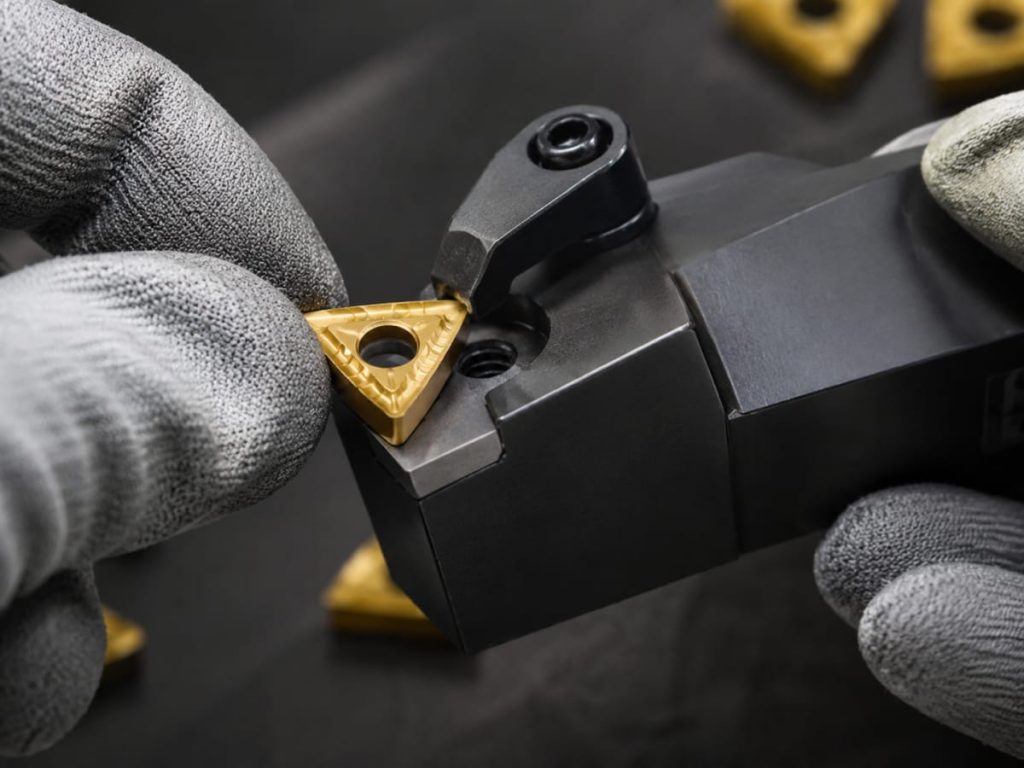
Manufacturers like TEAM Rapid often help customers connect part design with downstream operations because they also support finishing, assembly, packaging, and direct shipment. That broader view matters. A slightly revised rib or gate position may not only improve molding yield, but also improve assembly alignment and packaging protection.
Injection Molding Design Guidelines for OEM Customization, DFM Changes, and Production Scaling
Injection molding design guidelines are most valuable when they support change rather than resist it. In OEM development, the first CAD version is rarely the final one. Wall sections are adjusted, bosses are moved, textures are changed, clear windows are enlarged, inserts are added, and assembly methods evolve between prototype and full production. The supplier’s DFM capability determines whether those changes are handled early and economically or late and expensively.
A useful customization workflow usually follows this order: prototype evaluation, DFM review, tooling concept, first article sampling, validation changes, and production scale-up. TEAM Rapid fits well into this process because it supports both rapid manufacturing and production-oriented molding. A customer can begin with prototype verification, then move into tooling and molded production without changing the manufacturing partner midstream.
Typical DFM changes that improve moldability include:
- reducing thick sections by coring out non-functional mass
- adding draft to textured or deep features
- moving parting lines off cosmetic or sealing surfaces
- changing rib or boss proportions to reduce sink
- relocating gates to improve fill balance and cosmetics
- defining which tolerances are critical and which are reference only
TEAM Rapid’s detailed manufacturability analysis is especially useful here because the company reviews not just whether the part can be molded, but whether it can be molded efficiently. That includes identifying design risks before tooling, reducing quality problems, shortening development cycles, decreasing resin consumption, maximizing mold cavities, and optimizing cycle time.
Customization also includes mold strategy. A buyer may not need a full production steel tool on day one. Many programs start with low-cost MUD inserts or fast aluminum prototype molds, then move to P20, NAK80, or S136 steel tooling once demand is proven. TEAM Rapid offers this full tooling range, which gives OEMs more flexibility when demand is still developing.
For recurring production, injection molding design guidelines should also consider packaging, assembly orientation, part nesting, and inspection efficiency. A part that molds well but packs poorly or requires complex sorting can still create avoidable cost. Design for production scaling means thinking beyond the cavity and into the entire supply chain.
Sourcing Injection Molding Design Guidelines from China Without Compromising Quality or Logistics
Injection molding design guidelines are especially important when sourcing from China because the best offshore programs begin with clear engineering alignment, not just a low quote. If drawings are incomplete, critical features are not defined, or cosmetic expectations are vague, the supplier will either build extra risk into the price or move forward with assumptions that later create delays.
The right way to source from China is to send a complete RFQ package: 3D files, 2D drawings where required, resin specification, finish expectations, annual volume, critical dimensions, assembly notes, and any packaging or export constraints. Good suppliers will respond with DFM observations before tooling starts. Weak suppliers will quote too quickly and review too late.
A practical sourcing checklist should include:
- mold type recommendation: MUD, aluminum, or production steel
- resin and color confirmation, including any special grade needs
- gate, parting-line, and ejection strategy review
- first article and inspection plan
- finish requirements such as SPI, VDI, EDM texture, painting, plating, pad printing, or laser engraving
- export packaging, labeling, and shipping method
This is where suppliers like TEAM Rapid stand out. At TEAM Rapid’s Zhongshan factory in Guangdong Province, supported by a Hong Kong office and an integrated manufacturing resource network across China, buyers can combine tooling, molding, secondary operations, assembly, contract packaging, procurement support, limited warehousing, and direct shipping. That reduces handoff errors and helps keep design intent consistent from tool build to delivered parts.
Quality control is another reason sourcing discipline matters. TEAM Rapid is ISO 9001:2015 certified and supports full inspection and specification compliance, which is especially important for precision molded components. In practice, that means a buyer can pair custom injection molding with documented quality checks and faster communication when corrective actions are needed.
China sourcing works best when the supplier understands both technical requirements and international business expectations. TEAM Rapid has experience with Asian and Western business cultures, which helps with approval cycles, revisions, shipping communication, and production follow-up. For design-driven projects, that communication gap is often just as important as machine capacity.
Why Choose TEAM Rapid for Injection Molding Design Guidelines, Tooling, and Production
When companies need injection molding design guidelines translated into real manufacturing results, TEAM Rapid is a strong option because it combines DFM support, tooling flexibility, production capability, and responsive communication in one program structure. The value is not only that TEAM Rapid can mold parts. The value is that it can help customers make better design decisions before the tool is built.
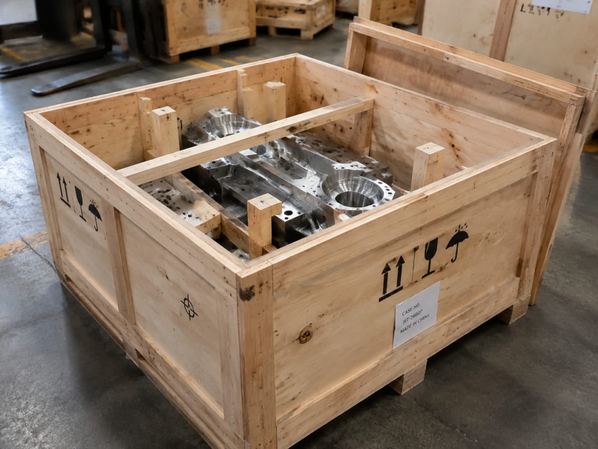
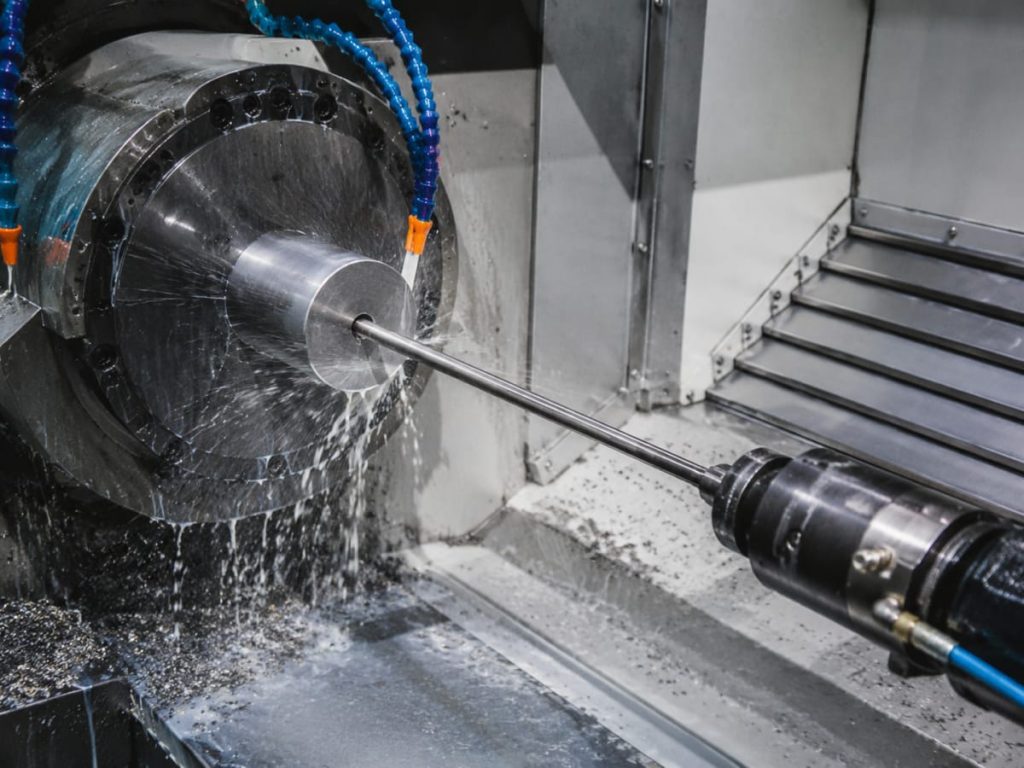
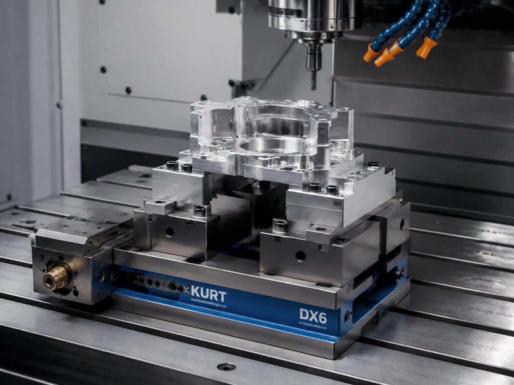
TEAM Rapid is a one-stop rapid manufacturing partner based in China, serving innovators, product designers, engineers, startups, and established global companies. Its broader capabilities include 3D printing, vacuum casting, CNC machining, rapid tooling, injection molding, die casting, aluminum extrusion, sheet metal fabrication, finishing, assembly, packaging, material management, procurement support, and direct shipping. That matters because many plastic part programs also need inserts, fixtures, cosmetic finishing, or downstream packaging support.
For molding programs specifically, TEAM Rapid offers:
- production quantities from 100 to 100,000+ parts
- diverse materials including ABS, PC, PP, PA/Nylon, POM, PEEK, TPU, TPE, and Silicone
- mold choices from MUD inserts to aluminum prototype molds and P20/NAK80/S136 steel tools
- standard molding tolerance around (\pm 0.05) mm, with tighter control available where justified
- tooling and first articles commonly in 5-25 days
- engineering response within a few hours through 1-to-1 support
TEAM Rapid also supports insert molding, overmolding, clear plastic parts, silicone molding, finishing, assembly, and packaging, which simplifies supplier management for international buyers. If a project starts with concept validation, the company can also bridge through Rapid Prototyping before moving into molded production.
From a sourcing perspective, TEAM Rapid remains attractive because it combines ISO-managed quality, competitive pricing, and practical lead times. For many buyers, the biggest benefit is fewer project handoffs and faster DFM feedback. If you are reviewing a new molded part or want a second opinion on design risk, you can request a quote, call +86 760 8850 8730, or email sales@teamrapidtooling.com.
Injection Molding Design Guidelines FAQ for Buyers and Engineers
What are the most important injection molding design guidelines for wall thickness?
The most important injection molding design guidelines for wall thickness are to keep sections as uniform as possible, avoid heavy mass transitions, and core out thick areas that do not add function. Uniform walls improve flow, cooling, shrink consistency, and cycle time. For many plastic parts, working somewhere in the 1.0-3.0 mm range is practical, while smaller precision parts often fall into the 0.8-2.0 mm band depending on resin and geometry.
How do injection molding design guidelines affect tooling cost?
Injection molding design guidelines affect tooling cost by controlling complexity. Missing draft, deep undercuts, poor rib design, overly tight tolerances, and gates placed in difficult locations all increase machining, fitting, sampling, and correction time. The best way to lower cost is to remove unnecessary tool actions and define only the tolerances that are critical to part function.
Which injection molding design guidelines improve part strength without adding weight?
The best injection molding design guidelines for strength are to use ribs, gussets, radii, and stable geometry instead of simply thickening walls. A well-designed rib network can add stiffness without creating the sink and long cooling times associated with heavy solid sections. Corner radii are also important because sharp internal corners concentrate stress and increase cracking risk.
Do injection molding design guidelines change by material?
Yes. Injection molding design guidelines change significantly by resin because materials differ in shrink rate, flexibility, flow behavior, moisture sensitivity, and cosmetic response. PP, ABS, PC, Nylon, POM, and PEEK should not be treated as interchangeable. Experienced suppliers such as TEAM Rapid usually review material choice alongside geometry so that the wall strategy, tolerance expectations, finish, and mold steel selection all align.
How do injection molding design guidelines apply to clear parts and overmolding?
For clear parts, injection molding design guidelines focus on polished steel, careful gate placement, resin drying, and protecting optical faces from weld lines, ejector marks, and flow disturbance. For overmolding, the design must also consider substrate stability, shutoff geometry, and material compatibility. TEAM Rapid is often a good fit for these programs because it supports both clear plastic molding with optical-grade finishes and insert/overmolding in one workflow.
When should injection molding design guidelines be reviewed with a supplier?
Injection molding design guidelines should be reviewed before tooling release, ideally once the part is functionally defined but still easy to modify. The earlier the DFM review happens, the easier it is to adjust draft, ribs, bosses, parting lines, gate location, and tolerance logic without expensive rework. Waiting until after the first mold trial usually adds time and cost.
Can injection molding design guidelines help shorten lead time?
Absolutely. Strong injection molding design guidelines shorten lead time by reducing tool rework, improving first-shot success, simplifying inspection, and preventing late-stage design corrections. A cleaner DFM package also helps the supplier choose the right tool strategy faster, whether that means a MUD insert, an aluminum prototype mold, or a production steel mold.
What lead time should buyers expect after finalizing injection molding design guidelines?
After the injection molding design guidelines are finalized and DFM is approved, many tooling plus first-article programs fall within 5-25 days depending on mold type and complexity. Faster prototype-oriented tools may be completed in 5-15 days. Buyers working with TEAM Rapid can also combine prototype validation, tooling, molding, finishing, and shipping support to reduce the total project timeline.
Content reviewed and updated: June 2026