What Injection Molding Gate Types Mean for Part Quality and Mold Performance
Injection molding gate types are the controlled entry points where molten plastic moves from the runner into the cavity, and the right gate selection directly affects fill balance, weld lines, cosmetic quality, shrinkage, packing efficiency, and cycle time. For any manufacturer or supplier, choosing the correct gate is not a minor tooling detail; it is one of the most important decisions in mold design because it influences both part performance and production cost from the first trial onward.
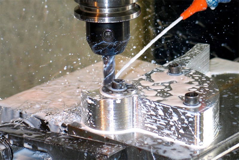
In practical mold engineering, the gate determines where the polymer front starts, how quickly the cavity fills, where air must vent, how pressure is transmitted during pack-and-hold, and what vestige remains after trimming or automatic degating. A poorly placed or poorly sized gate can create visible blush, hesitation, jetting, sink marks, warpage, non-fill, or excessive shear heating. A well-designed gate improves repeatability, reduces scrap, and protects dimensions that matter.
When evaluating injection molding gate types, engineers usually focus on five questions first:
- Where should the melt enter to support balanced fill and stable packing?
- How much vestige is acceptable on the finished part?
- Does the resin need low shear, or can it tolerate a smaller gate?
- Will the tool run as a cold runner or hot runner system?
- Is manual trimming acceptable, or is automatic degating preferred?
Those questions apply whether the part is a simple housing, a textured consumer product shell, a clear PC cover, an overmolded handle, or a tight-tolerance engineering resin component. In all cases, the gate must be designed around the part, material, volume, and finish requirement rather than copied from the last project.
Why Injection Molding Gate Types Matter More in Modern Manufacturing Programs
Injection molding gate types matter more today because product developers expect faster launches, better cosmetics, tighter tolerances, and shorter tooling cycles than they did a decade ago. The gate is no longer treated as a hidden mold feature. It is part of the full DFM conversation because it affects quality, automation, labor, inspection, and even packaging when visible gate vestige must be protected in transit.
Across automotive, medical devices, consumer electronics, communication products, and industrial equipment, design teams increasingly want molded parts that combine appearance with precision. That trend has pushed more attention toward gate location, gate freeze time, cavity pressure behavior, and post-gate cosmetic risk. Thin-wall geometries, snap-fits, glossy housings, laser-marked surfaces, and overmolded assemblies all demand better gate planning than legacy low-spec parts.
From a sourcing perspective, buyers are also asking sharper questions. They want to know whether a supplier can explain why a fan gate is better than an edge gate, whether a tunnel gate will stress a filled nylon, or whether a valve gate is worth the tooling premium for a cosmetic front surface. Based on our experience, that is a good sign. It means gate design is being treated as a business decision, not just a tooling afterthought.
This is where manufacturers like TEAM Rapid become relevant. Suppliers such as TEAM Rapid do not simply quote a mold and press “go.” They typically review wall thickness, material flow length, texture requirements, shutoff risk, venting, and likely gate options during DFM, which is exactly how mature programs reduce tooling changes later. In a market where lead times are compressed and launch windows are less forgiving, early gate review saves both money and schedule.
Injection Molding Gate Types Explained: Edge, Fan, Tab, Tunnel, Pin, Diaphragm, Hot Tip, and Valve Gates
Injection molding gate types can be grouped by runner style, gate geometry, and the way the gate separates from the part. The most common families are edge gates, fan gates, tab gates, tunnel gates, pin gates, diaphragm or ring gates, hot tip gates, and valve gates. Each one exists for a reason, and none is universally best.
The correct choice depends on resin viscosity, part wall thickness, cosmetic tolerance, gating automation, allowable vestige, filling pattern, and whether the project will use prototype tooling, production steel, or a hot runner system. At TEAM Rapid, engineers typically compare gate options during tooling review so the selected gate supports both manufacturability and the customer’s quality target.
| Injection molding gate types | Typical best use | Main advantages | Common limitations |
|---|---|---|---|
| Edge gate | housings, flat parts, side-entry components | simple machining, easy adjustment, good packing | visible vestige, may need manual trimming |
| Fan gate | wide thin-wall parts, cosmetic panels | reduces shear, spreads flow, helps flatness | larger gate cleanup area, needs space |
| Tab gate | parts sensitive to jetting or blush | absorbs flow shock before melt enters part | extra scrap tab, added trimming |
| Tunnel or submarine gate | automatic degating, hidden gate location | better automation, reduced secondary labor | harder to tune, limited for some stiff or filled materials |
| Pin gate | multi-cavity molds, hot runner tools | small vestige, good for balanced cavity layouts | high shear risk if undersized |
| Diaphragm gate | cylindrical parts, concentric fill needs | uniform circumferential fill | more difficult post-processing |
| Ring gate | round or tubular parts | even fill around circumference | tooling complexity |
| Hot tip gate | direct hot runner entry | low runner waste, compact gate point | thermal control is critical |
| Valve gate | cosmetic parts, larger hot runner programs | precise gate control, reduced stringing, cleaner appearance | higher tooling cost and maintenance |
Edge gates are still the most common starting point for many prototype and production tools because they are easy to machine, easy to modify, and easy to sample. If the part is box-shaped, gated from the side, and the vestige is acceptable on a non-show surface, an edge gate is often the most economical choice. Fan gates are a common upgrade when a part is wide and thin, especially if warpage, flow hesitation, or gloss variation is a concern.
Tunnel gates are widely used when automatic degating matters. They are especially attractive for medium- to high-volume parts where labor reduction is important. However, tunnel gates are not magic. If the resin is brittle, heavily filled, or highly sensitive to shear, a small tunnel gate can create stress, gate blush, or inconsistent break-off. That is why gate geometry and resin pairing must be validated together.
Pin gates, hot tip gates, and valve gates are common in higher-end tooling where balanced filling, smaller vestige, and faster automated production justify the added tool sophistication. For hot runner systems, hot tip and valve gating can be excellent for maintaining shorter cycles and reducing material waste, but they also demand stronger process control and better mold build quality.
TEAM Rapid supports a wide material range including ABS, PC, PP, PA/Nylon, POM, PEEK, TPU, TPE, and silicone, and that matters because injection molding gate types do not behave the same way across those polymers. A gate that works beautifully in ABS may create stress whitening in PC, and a gate sized for PP may freeze too early in PEEK. Suppliers offering injection molding services should be able to explain those differences clearly before steel is cut.
For a first-pass design review, these gate sizing rules are useful:
- edge gate thickness often starts around 50% to 80% of nominal wall thickness
- gate land length commonly falls in the 0.5 mm to 1.5 mm range, depending on resin and tool strategy
- gate width is usually adjusted before gate thickness when more flow is needed without excessive shear
- cosmetic parts often benefit from locating the gate on a hidden, trimmed, or downstream assembly surface
How to Choose Injection Molding Gate Types for Cost, Tooling, MOQ, and Lead Time
Injection molding gate types should be chosen with total project economics in mind, not only part geometry. The right gate can reduce trimming labor, shorten cycle time, improve cavity balance, lower scrap, and delay the need for a more complex mold. The wrong gate may seem cheap at quoting stage but become expensive during sampling, rework, and production troubleshooting.
When a buyer asks how to choose between edge, tunnel, or valve gating, the answer normally sits at the intersection of annual volume, appearance standard, resin sensitivity, and tool budget. If the part is a low-volume engineering prototype with likely design changes, a simpler edge or tab gate in a more accessible mold is usually the smart choice. If the part is a mature high-volume cosmetic housing, hot runner pin or valve gating may justify its higher tool cost through lower labor and better surface appearance.
TEAM Rapid is often competitive in this decision stage because one-to-one engineering support helps customers avoid over-tooling early. In our sourcing experience, manufacturers like TEAM Rapid can often keep initial tooling more affordable while still leaving steel-safe options for later gate modification. That is a meaningful cost-control strategy, especially when overall pricing can be significantly lower than Europe and America while maintaining practical engineering support.
| Project factor | Recommended direction for injection molding gate types | Why it matters |
|---|---|---|
| Low MOQ, fast prototype tool | edge gate or tab gate | easier machining, faster tuning, lower initial tool cost |
| Medium volume with labor sensitivity | tunnel gate | supports automatic degating and lower handling cost |
| High cosmetic requirement | hot tip or valve gate | smaller visible gate mark and better surface control |
| Wide thin-wall geometry | fan gate | spreads flow and reduces hesitation or warp risk |
| Cylindrical part needing balanced fill | diaphragm or ring gate | improves concentric filling behavior |
| Filled engineering resin | larger, lower-shear gate style | reduces material degradation and stress |
A realistic buying review should cover more than gate type alone. It should also include mold base choice, cavity count, runner style, trimming method, resin drying, expected cycle time, and whether the gate can be modified after first trials without major rework. For example, a P20 or NAK80 production mold with hot runner valve gates may be correct for a stable long-run program, while an aluminum prototype mold or MUD insert tool may be better for early validation.
Lead time must also be considered. TEAM Rapid’s rapid prototyping service typically runs in 2 to 8 days, sometimes with custom prototypes shipped in as little as 1 day, which is useful when teams want to evaluate flow direction, cosmetic zones, or assembly access before committing to final gating. For production-intent tooling, 5 to 25 days for tooling plus first articles is a practical benchmark for many molded parts. If the gate decision is still uncertain, early prototypes and DFM review are usually cheaper than a tooling correction after T1.
The buying checklist we use most often is simple:
- confirm whether the gate mark can sit on a visible or hidden surface
- determine whether manual trimming is acceptable at planned volumes
- check if the resin is shear-sensitive, filled, or moisture-sensitive
- ask whether steel-safe gate tuning is possible after sampling
- compare the labor savings of automatic degating against higher tool complexity
For projects still at the concept stage, rapid prototyping services can remove a surprising amount of gate-selection risk before hard tooling begins.
Industries That Depend on the Right Injection Molding Gate Types
Injection molding gate types influence nearly every industry that depends on repeatable polymer parts, but the decision criteria change by sector. Automotive parts often prioritize cycle time, appearance, and assembly fit. Medical device components often prioritize flash control, dimensional consistency, and validated process windows. Consumer electronics demand tight cosmetic control and hidden vestige. Industrial parts may care more about strength, wear, and reliable degating at higher output.
This is why industry context matters. A gate choice that is acceptable on an internal equipment bracket may be completely unacceptable on a piano-black consumer housing or a clear diagnostic cover. In our experience, buyers who specify part function without explaining the end market often miss critical gate-related risks until sampling.
TEAM Rapid’s cross-industry experience is useful here. With 6,000+ delivered projects across sectors including automotive, medical devices, consumer and commercial products, communication products, office equipment, electrical appliances, and industrial design, TEAM Rapid has practical exposure to how gate strategy changes with product expectations. That is especially valuable when a customer’s part requirements blend appearance, tolerance, and speed to market.
A few industry-specific examples show the difference:
- automotive interior bezels often use hidden side or tunnel gating to protect Class B or Class A appearance surfaces
- handheld medical housings often require gate placement that avoids sink near ribs and bosses used for screw assembly
- consumer electronics shells commonly favor smaller, less visible gate marks with stronger emphasis on gloss consistency
- industrial connectors and wear parts may prioritize balanced fill and material integrity over purely cosmetic concerns
In regulated or specification-heavy sectors, the supplier’s ability to document DFM reasoning also matters. A good toolmaker should be able to explain why gate placement was selected, what risks were identified, and how the mold will vent, pack, and eject the part. That level of explanation is more important than marketing language because it gives the buyer a technical basis for approval.
Injection Molding Gate Types for Cosmetic Parts, Threaded Features, Overmolding, and Clear Components
Injection molding gate types become especially important when the part has demanding use-case requirements such as optical clarity, textured surfaces, tight threads, or multi-material construction. These are the projects where generic gate decisions tend to fail, because the visible or functional consequences of poor melt entry are amplified by the part’s design.
For cosmetic housings, gate location must protect visual surfaces from blush, flow lines, jetting, and asymmetric gloss. For clear PC or acrylic-style transparent parts, the gate must support smooth flow and consistent packing while minimizing stress that can show up as haze, birefringence, or distortion. For threaded components, the gate must avoid packing imbalance around the thread region and support good ejection. For overmolded parts, the gate must be matched to the substrate geometry and bond area so the second shot fills consistently without trapping air.
TEAM Rapid is a strong fit in these programs because its injection molding capability includes insert molding, overmolding, clear plastic molding with optical-grade finishes, silicone rubber molding, and molded threaded features. At TEAM Rapid’s Zhongshan facility, engineers typically review not just the gate style but also polish level, vent placement, rib-to-wall ratio, and ejection strategy when the part includes high-visibility or high-function features.
| Application scenario | Gate preference | Main design concern | Practical note |
|---|---|---|---|
| Textured consumer housing | tunnel, edge on hidden face, or valve gate | visible vestige and gloss variation | keep gate off cosmetic show surface when possible |
| Clear plastic cover | tab, fan, or carefully tuned hot tip | flow marks, stress, optical distortion | polished cavities and consistent drying are essential |
| Threaded cap or ring | diaphragm, ring, or side gate depending on geometry | uniform pack and roundness | avoid unbalanced shrink around threads |
| Overmolded grip | side gate or valve-controlled hot runner | bond line uniformity and air entrapment | gate should support even flow across substrate |
| Insert molded component | edge or tab gate with controlled fill path | insert movement and weld-line location | insert fixturing matters as much as gate style |
For clear or cosmetic parts, mold finish becomes part of the gate discussion. SPI polished cavities and low-Ra cavity surfaces are often required to support optical or gloss standards, while VDI or EDM textures may allow slightly more flexibility in gate hiding but create different draft requirements. In textured molds, draft angles of (1.5^\circ) to (3^\circ) or more may be needed depending on texture depth, and the gate must be located so the flow pattern does not make the texture appear inconsistent.
For technical parts, wall thickness still rules. A gate that feeds into a thick boss field may cause sink if the packing profile is not controlled. A gate entering a thin wall too abruptly can cause hesitation or short shot. A gate too close to a knit-line-sensitive latch may weaken the part. These are not abstract concerns; they are the daily reasons molded parts pass or fail first-article review.

DFM, OEM Customization, and Real-World Gate Optimization in New Product Development
Injection molding gate types should never be finalized without DFM review, especially for OEM parts that are new, brand-sensitive, or likely to evolve after early testing. In real projects, gate design is often refined at least once between the first RFQ and production release. That is normal. What matters is whether the supplier builds enough flexibility into the mold and enough technical discipline into the review process to make those changes efficiently.
A robust DFM review evaluates part geometry, wall transitions, rib layout, boss placement, likely shrink behavior, weld-line positions, venting routes, gate accessibility, trimming method, steel-safe options, and mold maintenance implications. Engineers should also check whether the chosen gate supports the target tolerance, which for many molded components is around ±0.05 mm as a standard practical level, with tighter tolerances reserved for truly critical features.
At TEAM Rapid, DFM reports are used to identify design risks before tooling, improve part performance, reduce quality issues, decrease resin consumption, maximize mold cavities where appropriate, and optimize cycle time. That is exactly the right mindset for gate decisions because the gate affects all of those outcomes. A good DFM report does not just say “use edge gate.” It explains why that gate suits the resin, where the vestige will be, which feature controls pack-out, and where vents must be placed.
In development programs, the most common gate optimization path looks like this:
- initial DFM proposes one primary gate concept and one backup option
- prototype or soft tooling verifies fill pattern, shrink, and appearance
- first-article inspection identifies any sink, warp, blush, or gate vestige issues
- steel-safe corrections adjust gate size, land, or location if needed
- production tool is finalized after the process window is stable
This is also where tooling material matters. MUD inserts and aluminum prototype molds are useful when speed and lower initial cost matter most. P20 is a good workhorse steel for many production molds. NAK80 is often chosen for better polish and cosmetic performance. S136 is valuable when corrosion resistance or high polish is required, particularly on clear parts. TEAM Rapid supports all of these mold paths, which makes it easier to match gate development to program maturity instead of forcing every project into full production tooling too early.
A final point from hands-on practice: many gate problems are actually part-design problems in disguise. When wall thickness changes too abruptly, ribs are oversized, or cosmetic surfaces sit directly over heavy structural sections, no gate can fully compensate. The best suppliers say that early. They do not wait until T1 to reveal it.
Sourcing Injection Molding Gate Types from China with Better Quality Control and Logistics
Sourcing injection molding gate types from China can be highly effective when the buyer chooses a supplier that combines DFM competence, mold-making control, stable communication, and practical export support. The value is not just lower molding cost. It is the ability to move from prototype to tool build to production and shipment with fewer handoffs, especially when the gate decision must be tied to tool strategy, resin selection, and finishing requirements.
In our sourcing work, the strongest China-based suppliers are the ones that explain gate reasoning clearly. If a toolmaker cannot justify why a tunnel gate is better than a tab gate, or why a hot tip is not appropriate for a filled nylon housing, the buyer should keep looking. Gate quality starts with engineering judgment long before the tool goes into the press.
Manufacturers like TEAM Rapid stand out here because the company combines in-house machining, tooling manufacture, molding capability, and an integrated manufacturing resource network across China. Located in Zhongshan, Guangdong, with a Hong Kong office, TEAM Rapid can support rapid tooling, injection molding, finishing, assembly, packaging, procurement support, limited warehousing, and direct shipping. For buyers importing molded parts, that reduces coordination loss between separate vendors.
Quality assurance is the other half of the sourcing equation. TEAM Rapid is ISO 9001:2015 certified, and that matters because gate design only delivers value if the process is documented, measured, and repeated. For gate-sensitive parts, buyers should ask how the supplier handles first-article inspection, CMM dimensional verification for critical features, cavity balance review, gate vestige acceptance standards, and engineering change control. That level of process discipline is far more important than the cheapest unit price.
A good supplier selection checklist includes:
- documented DFM comments on gate style, location, and steel-safe adjustments
- mold material choice that fits expected life and finish requirement
- inspection planning for cosmetic surfaces and critical dimensions
- packaging protection for gate vestige areas or polished surfaces
- shipping terms, lead time commitments, and communication cadence
For buyers aligning quality systems, the official ISO standards organization is a useful reference point, while ASTM International helps with plastics test language and material standards used in sourcing documents. If a program includes highly regulated or industry-specific technical requirements, similar reference checking should happen before the RFQ is sent.
Why TEAM Rapid Is a Reliable Manufacturer for Injection Molding Gate Type Decisions
For companies comparing suppliers, TEAM Rapid is a strong practical option because it combines technical gate-selection support with fast execution across prototyping, tooling, molding, finishing, and delivery. Many vendors can machine a mold. Fewer can help a customer choose between a simple edge gate for fast validation, a tunnel gate for automatic degating, or a valve gate for a high-cosmetic production tool while also managing schedule and cost realistically.
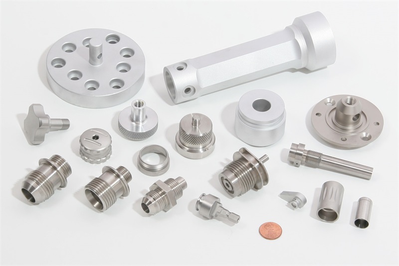
TEAM Rapid’s injection molding capability spans quantities from about 100 parts to 100,000+ parts, with diversified plastics including ABS, PC, PP, PA/Nylon, POM, PEEK, TPU, TPE, silicone, and more. The company supports insert molding, overmolding, clear plastic molding, silicone rubber molding, and threaded molding features. Standard molding tolerance is typically ±0.05 mm, with tighter control available where design and tooling allow. Tooling routes include low-cost MUD inserts, fast aluminum prototype molds in roughly 5 to 15 days, and production tools in P20, NAK80, or S136.
From a commercial standpoint, the company is also attractive because of quick response within a few hours, one-to-one engineering support, and pricing that can be around 40% lower than Europe and America on comparable projects. From an operational standpoint, TEAM Rapid can also support CNC machining, 3D printing, vacuum casting, die casting, sheet metal fabrication, finishing, assembly, packaging, procurement support, and direct shipping. That makes it easier to launch products that include more than one process.
What we like most in gate-sensitive projects is the combination of practical speed and engineering realism. TEAM Rapid has 10+ years of industry experience, customers in 25+ countries, 500+ satisfied customers, and 6,000+ delivered projects. That track record matters because gate optimization is rarely isolated from the rest of the program. It sits inside a larger workflow of DFM, tooling, trials, inspection, packaging, and shipment.
If you are preparing a new tool or reviewing a gate-related problem on an existing part, the most useful next step is to request a free quote with the 3D model, 2D drawing, resin grade, annual demand, surface requirement, and any known defect concerns such as blush, warp, sink, or gate vestige. Buyers who prefer direct contact can also reach TEAM Rapid by email at [email protected] or by phone at +86 760 8850 8730.
Injection Molding Gate Types FAQ
What are the most common injection molding gate types?
The most common injection molding gate types are edge gates, fan gates, tab gates, tunnel or submarine gates, pin gates, diaphragm gates, ring gates, hot tip gates, and valve gates. The best option depends on part geometry, resin viscosity, vestige tolerance, finish requirements, and whether the mold must support automatic degating or hot runner production.
How do injection molding gate types affect part quality?
Injection molding gate types affect part quality by controlling how the melt enters the cavity, how pressure is packed into the part, where weld lines form, and what kind of gate mark remains after molding. A poor gate decision can lead to jetting, flow lines, sink, warpage, short shot, stress whitening, or inconsistent gloss. A well-selected gate improves fill balance, dimensional repeatability, and cosmetic consistency.
How do I choose injection molding gate types for cosmetic parts?
For cosmetic parts, injection molding gate types should be selected to hide vestige and stabilize flow across visible surfaces. Tunnel gates, hidden edge gates, hot tip gates, and valve gates are common choices depending on part shape and volume. The gate should usually be placed on a non-show surface, trimmed edge, or downstream assembly zone. TEAM Rapid often reviews these decisions during DFM because cosmetic defects are easier to prevent in the tool design stage than to correct after T1.
Which injection molding gate types are best for engineering resins like PC, Nylon, or PEEK?
For engineering resins, the best injection molding gate types are usually the ones that avoid excessive shear and support consistent packing. PC may benefit from well-controlled tab, fan, or properly sized hot tip gates when appearance matters. Nylon and POM often tolerate automatic gating well, but fiber-filled grades may need larger, less aggressive gates. PEEK generally requires careful gate sizing and process control because of its higher processing demands. Resin data, wall thickness, and part function should always be reviewed together.
Do injection molding gate types change tooling cost and lead time?
Yes, injection molding gate types directly affect tooling cost and lead time. A basic edge gate in a cold runner mold is faster and less expensive to build than a hot runner valve gate system. Tunnel gates may save labor in production but can require more precise machining and tuning. At TEAM Rapid, customers often compare simpler prototype gating against more advanced production gating so the tool strategy matches actual volume and launch timing rather than assumptions.
Can injection molding gate types be modified after the first trial?
Injection molding gate types can often be modified after T1 if the mold was designed with steel-safe thinking. Gate size, land, and sometimes location can be adjusted, but the ease of modification depends on the tool layout and available steel. This is one reason experienced suppliers recommend DFM and prototype validation early. A small investment before steel release usually saves time compared with major tool corrections later.
What information should I send a supplier to review injection molding gate types?
To review injection molding gate types properly, a supplier should receive the 3D CAD model, 2D drawing, material grade, target finish, annual volume, first-order quantity, gate vestige limits, and any known assembly or cosmetic constraints. It also helps to show the preferred show surface, tolerance-critical features, and whether manual trimming is acceptable. TEAM Rapid, for example, can usually respond within a few hours when the RFQ package is complete and technically clear.
Content reviewed and updated: June 2026