
Custom Plastic Knob – Rapid Tooling & Low-Volume Injection Molding Case
Looking for a cost-effective tooling solution for custom plastic knobs at small-volume? This case study demonstrates how we delivered T1 samples in just 14 days for a PA66 (Nylon) plastic knob with critical dimensions — at a low tooling cost.
This project is a perfect example of how low-volume plastic injection molding services can bridge the gap between prototyping and mass production.
Project Details
Parameter
Details
Part Name
Plastic Knob
Part Size
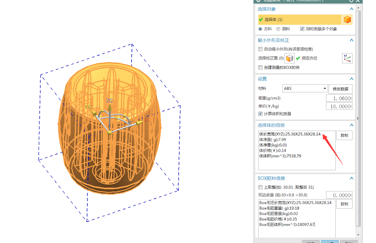
25 × 25 × 28 mm
Part Material
PA (Polyamide / Nylon)
Process
Rapid Tooling & Low-Volume Injection Molding
T1 Sample Leas Time
14 Working Days
Tooling Material
P20 Pre-hardened Steel
Tooling Life
50,000 cycles
Mold Structure
Multi-Cavity
Runner System
Cold Runner
Gate Type
Submarine (SUB) Gate
Rapid Tooling Design – Key Considerations
Good rapid tooling design is the foundation of fast delivery, low cost, and stable part quality. Here's how we approached the mold design for this custom PA66 knob:
 DFM (Design for Manufacturability) Analysis
Before cutting steel, we performed a thorough DFM review with the client:
- Wall thickness: Kept uniform at 1.5–2.0mm to ensure even filling and minimize sink marks
- Draft angle: Applied 1°–2° on all vertical surfaces for smooth ejection
- Ribs & bosses: Designed with thickness ≤ 60% of adjacent wall to avoid sink
- Corner radii: Added minimum R0.5 to reduce stress concentration and improve material flow
Cavity Layout & Balancing
- Multi-cavity layout was chosen to maximize output per cycle
- Runner lengths were balanced to ensure equal fill pressure and packing to each cavity
- Cavity spacing optimized for adequate cooling and ejection clearance
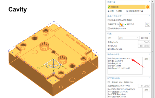
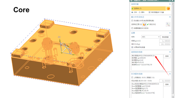
- Layout arranged symmetrically within the MUD insert to maintain balanced clamping force
 Gate Design – Submarine (SUB) Gate
- Gate placed on the non-visible bottom surface of the knob
- Gate size: Ø0.8mm – carefully sized to balance fill speed vs. gate vestige
- Auto-degating during ejection → no secondary trimming operation
- Gate land kept short to minimize pressure drop and shear heat
Runner System Design
- Cold runner selected for cost efficiency
- Runner diameter: Ø4–5mm (sized to minimize material waste while ensuring proper packing)
- Rounded runner profile to reduce pressure loss and ease ejection
- Runner layout kept as short as possible to reduce cycle time and material cost
- Runner positioned within MUD insert boundary to avoid frame interference
 Cooling Channel Design
Even in rapid tooling, proper cooling is critical for:
- Cycle time reduction
- Meet the specification of MUD
- Dimensional stability (especially important for PA which shrinks ~1.0–1.5%)
- Preventing warpage on the knob's flat surfaces
Our design approach:
- Cooling channels placed as close to the cavity surface as possible (typically 3–5mm from cavity face)
- Channel diameter: Ø8mm, with uniform spacing
- Baffle/bubbler used in core areas where straight-through channels are not feasible
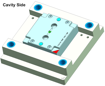
- Separate cooling circuits for core and cavity side for independent temperature control
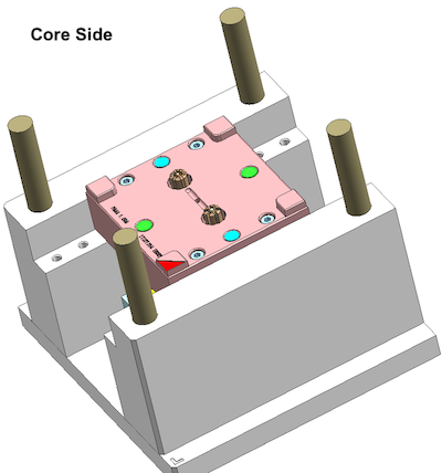
Ejection System Design
- Ejector pins placed on non-critical surfaces to avoid visible marks
- Ejection force calculated based on draft angle, surface area, and PA's shrinkage onto the core
- Added ejector plate return springs for reliable reset
- Knockout pattern balanced to prevent part distortion during ejection
Venting
- Venting slots (0.02–0.03mm depth) added at the end of fill and along parting line
- Critical for PA material to prevent burns, short shots, and trapped gas
- Submarine gate area also vented to allow air escape during initial fill
Shrinkage Compensation
- PA shrinkage rate: 1.0% – 1.5% (varies with grade and glass fiber content)
- Mold dimensions enlarged accordingly based on material datasheet and our experience
- Critical dimensions (bore ID, outer diameter) given extra attention with trial-and-adjust strategy at T1
Results
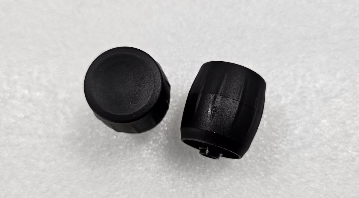
T1 samples in 15 days
All critical dimensions passed on first trial
50,000 cycles of consistent quality
Zero post-processing required
No warpage or sink marks
Tooling cost 60–70% lower than full custom hard tooling
FAQ
Q: What is rapid tooling design?
A: It's the mold design process optimized for speed and cost, using P20 or aluminum, with simplified structures while maintaining part quality for low-volume production.
Q: How is rapid tooling design different from production tooling?
A: Rapid tooling prioritizes simplicity, faster machining, and lower cost. Complex actions (slides, lifters) are minimized by manual insert. Surface finish and tolerance requirements are balanced against budget.
Q: Can I use rapid tooling for engineering plastics like PA, POM, or PC?
A: Yes! P20 steel works well with most engineering plastics including PA (Nylon), POM (Delrin), PC, ABS, PP, and more. For highly abrasive or corrosive materials, we may recommend surface treatment or a harder steel.
Q: What is the minimum order quantity for low-volume injection molding?
A: We accept orders starting from as low as 100 pieces. Our rapid tooling solutions are designed for volumes ranging from hundreds to tens of thousands.


 Contact