
Why Does an Injection Mold Flash? Causes and How to Prevent It
Injection mold flash occurs when molten plastic escapes the mold cavity through gaps at the parting line, ejector pins, vents, or slides—typically caused by excessive injection pressure, insufficient clamp force, worn tooling, or low-viscosity resin—and the most effective way to prevent plastic injection molding flash is to optimize injection speed and holding pressure, maintain proper mold shutoff contact, and ensure clamp tonnage exceeds the projected cavity force.
As one of the common defect in plastic injection molding, injection mold flash usually results in extra rework, scrapped parts, and delayed shipments. This guide covers the main causes of injection mold flash and practical ways to reduce or prevent it in production.
What Is Injection Mold Flash
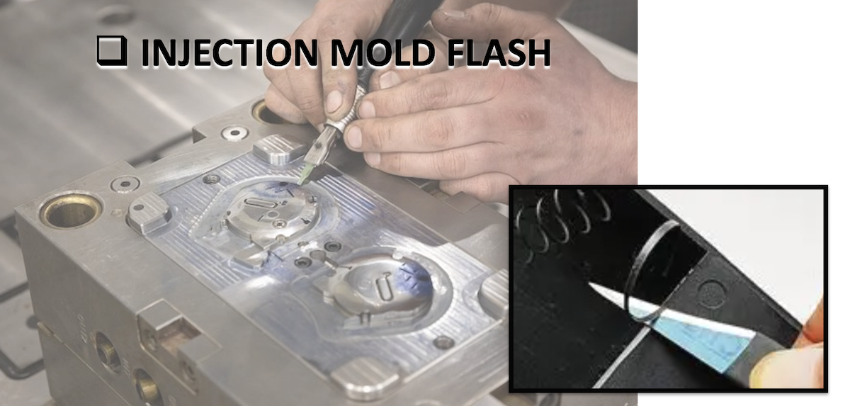
Flash in injection molding is excess plastic that extends beyond the intended part geometry. It usually forms where mold surfaces meet and leave a gap, even a very small one. Cavity pressure pushes molten resin into the gap, leaving a thin fin on the finished part.
What Does Flash Look Like on Plastic Parts
Flash appears as a thin fin or web along the parting line, around ejector pins, near inserts, or at slide interfaces. In more severe cases, it can form a skirt around the entire part perimeter. Flash thickness typically ranges from 0.02 mm to 0.5 mm, depending on the gap size and injection pressure.
Flash is usually easy to see on transparent or light-colored resins. On dark or textured parts, it may not show up until dimensional inspection or assembly.
Why Is Flash a Problem in Injection Molded Parts
Flash can affect both dimensional accuracy and assembly fit. A layer as thin as 0.1 mm may prevent a snap fit from engaging or interfere with mating components. In medical, automotive, and electronics applications, that interference can cause a functional failure.
Flash also adds post-processing cost. Manual trimming, deburring, or secondary machining takes time and can damage the part's surface. In high-volume production, even a low flash rate can add up to substantial scrap and rework costs.
Flash vs. Burrs, Short Shots, and Other Molding Defects
Flash and burrs can look similar, but they have different causes.
- Burrs typically result from mechanical damage or wear at a mold edge.
- Flash forms when molten plastic escapes through a gap under pressure.
A short shot is the opposite problem: the cavity does not fill completely because of insufficient material or pressure.
Sink marks, weld lines, and voids are separate surface or internal defects; they are not caused by plastic escaping the cavity. Identify the defect before choosing a corrective action. If flash is mistaken for a burr, for example, unnecessary mold polishing may follow while the actual issue—such as clamp force or venting—goes unaddressed.
How to Diagnose Flash in Injection Molding
Before changing machine settings or sending the mold for repair, work through the problem methodically. Flash in injection molding rarely has just one possible cause. It often results from a combination of mold condition, machine capability, material behavior, and process settings.
Record where the flash appears, how thick it is, and how often it occurs. Then check the factors below one by one.
Identify Where the Flash Forms
Flash location is one of the best clues to its cause. Flash along the parting line may indicate insufficient clamp force, mold deflection, or worn shutoff surfaces. Flash around ejector pins often points to excessive pin clearance or worn pin bores.
Flash near a vent may mean the vent is deeper than the material's flow threshold allows. Flash at slides or lifters can indicate worn mating surfaces, poor fit, or misalignment. Matching the flash location to the relevant mold feature helps narrow the investigation.
Material Viscosity and Plastic Resin Selection
Low-viscosity resins, including nylon, and some TPE grades, can be more prone to flash because they flow into small gaps more readily. Resins with a high melt flow index (MFI) generally require tighter mold shutoffs and closer process control.
Moisture-sensitive resins such as PA6, PA66, and PET can show reduced viscosity if they are not dried properly, making flash more likely. Check drying conditions and look for viscosity differences between material lots before attributing the problem to the mold or machine.
How to Prevent Plastic Injection Molding Flash
Start by optimizing the process. Move on to tooling repairs or machine-capacity changes only if the evidence points in that direction. This sequence helps limit downtime and avoid unnecessary mold modifications.
Optimize Injection Speed and Pressure
Lower injection speed and peak pressure in small steps, checking that the cavity still fills completely after each change. A slower fill can reduce the instantaneous pressure at the parting line and the force driving plastic into gaps. Watch for short shots or incomplete filling as you adjust the settings.
Use a scientific molding approach where practical. Establish a viscosity curve, set the pressure limit just above what is needed to fill the cavity, and define a stable process window. This gives the team a data-based starting point instead of relying on trial and error.
Optimize Holding Pressure and Packing Time
Excessive holding pressure is a common cause of plastic injection molding flash, particularly near the gate and along the parting line. Reduce it in small steps of 5–10%, then check part weight, critical dimensions, and gate-freeze behavior after each adjustment.
Reducing packing time may also help once the gate has frozen. Use a gate-freeze study to establish the shortest effective packing duration. Over-packing can contribute to flash while also increasing residual stress and cycle time.
Why Insert Molding and Overmolding Are More Prone to Flash
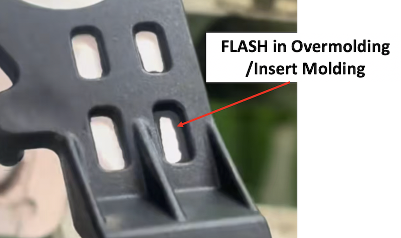
Insert molding and overmolding introduce additional parting interfaces that are not present in standard two-plate or three-plate molds. These extra interfaces create more potential escape paths for molten resin, making injection mold flash a higher-risk defect in these processes.
Why Flash Is More Common Around Inserts
In insert molding, a metal or pre-molded component is placed into the cavity before injection. The gap between the insert outer diameter and the mold cavity wall forms a natural shut-off edge. If that gap exceeds the material's flow threshold—even by 0.02 mm—resin will penetrate and form flash around the insert.
Thermal expansion mismatch is a frequent contributor. Metal inserts expand during mold heating, while the surrounding cavity steel expands at a different rate. This can open or close the shut-off gap unpredictably across the production cycle.
Insert placement tolerance also matters. If the insert is not seated consistently in its pocket, one side of the shut-off may open while the other remains closed, producing flash on only one side of the part.
Flash at the Overmold Boundary
In overmolding, the second-shot material flows over or around a substrate part. Flash typically appears at the boundary where the overmold material meets the substrate edge. This happens when the substrate has warped, shrunk beyond tolerance, or when the shut-off edge on the overmold cavity is worn.
Soft substrates such as TPE or silicone are especially vulnerable. The injection pressure of the overmold material can deflect the substrate slightly, opening a momentary gap that allows flash to form.
How to Prevent Flash in Insert Molding and Overmolding
|
Strategy |
Application |
|
Tighten insert-to-cavity clearance |
Keep the shut-off gap below the material's flash threshold |
|
Add insert retention features |
Use knurls, undercuts, or mechanical locks to hold the insert in a repeatable position |
|
Control thermal expansion |
Preheat inserts to reduce the temperature differential, or design the shut-off gap to account for expansion at molding temperature |
|
Verify substrate flatness |
For overmolding, inspect substrate warpage before the second shot; reject or rework parts outside tolerance |
|
Optimize second-shot pressure |
Reduce injection speed and holding pressure on the overmold shot to minimize deflection of the substrate |
|
Maintain shut-off edges |
Inspect and polish shut-off lands regularly; replace worn inserts or cavity blocks before flash becomes chronic |
Design Considerations to Reduce Flash Risk Early
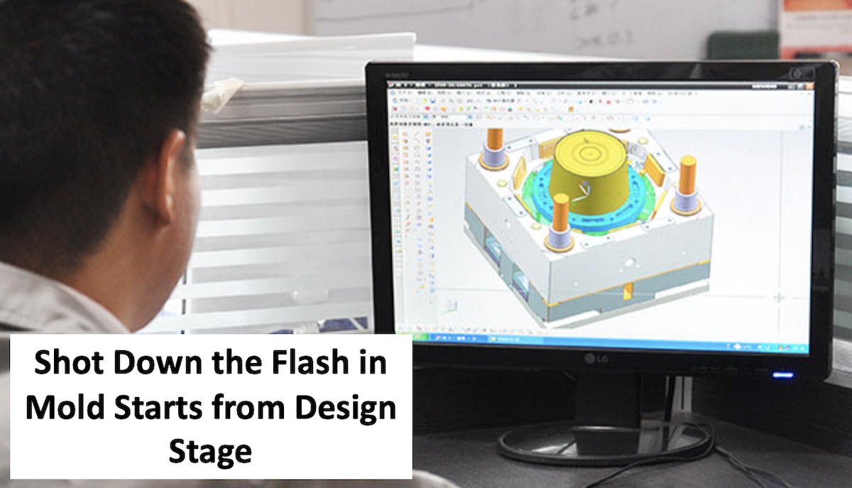
The most effective flash prevention in insert molding and overmolding starts at the design stage. Specify insert tolerances that account for thermal growth at molding temperature. Design shut-off edges with a slight interference or a stepped geometry rather than a flat butt joint, which is more forgiving of minor misalignment.
For overmolding, include a mechanical interlock or a lip on the substrate that the overmold material flows over. This creates a positive seal that is less dependent on edge-to-edge contact precision.
Running a mold flow analysis for injection molding before cutting steel can reveal high-pressure zones near inserts or overmold boundaries, allowing your team to adjust gate location, vent placement, or shut-off geometry before the first trial shot.
Injection Mold Flash Troubleshooting Checklist
Use this table as a quick reference during production troubleshooting. Match the symptom to a likely cause, perform the suggested check, and then apply the appropriate corrective action.
|
Observed Symptom |
Likely Cause to Investigate |
Recommended First Check |
Corrective Action |
|
Flash around the parting line |
Excessive cavity pressure, insufficient effective clamp force, or poor mold shutoff contact |
Review the pressure profile, clamp tonnage settings, and mold shutoff contact |
Increase clamp force, reduce injection/holding pressure, or repair parting-line shutoff surfaces |
|
Flash near an ejector pin |
Worn or excessive clearance around the pin |
Inspect pin fit, wear, and local tooling condition |
Replace or resize ejector pins, polish the pin bores, or add pin locks |
|
Flash around a slide |
Worn shutoff, poor fit, or misalignment |
Inspect mating surfaces and alignment |
Repair or replace slide shutoffs and realign the slide components |
|
Flash near a vent |
Excessive vent depth, damaged vent land, or excessive local pressure |
Inspect vent geometry and filling conditions |
Reduce vent depth to a material-appropriate level and repair the vent land |
|
Flash appears randomly across multiple locations |
Process variation, contamination, or material inconsistency |
Compare cycle data, material lot records, and barrel temperature stability |
Stabilize process settings, verify material drying, and check the hopper and barrel for contamination |
Frequently Asked Questions About Injection Mold Flash
Q: What is the most common cause of injection mold flash?
A: The most common cause is excessive injection or holding pressure combined with a marginal shutoff gap at the parting line. When cavity pressure exceeds what the clamp force can contain, the mold halves separate slightly and molten resin escapes. Worn parting-line surfaces and insufficient clamp tonnage are the next most frequent contributors.
Q: How much flash is acceptable in injection molding?
A: There is no universal standard. Acceptable flash limits depend on the application, material, and customer specification. For most commercial parts, flash below 0.05 mm may be acceptable if it does not affect assembly or function. Medical, automotive, and electronics applications often require zero flash or limits below 0.02 mm.
Q: Can injection mold flash be fixed without repairing the mold?
A: Yes, in many cases. If the flash is caused by excessive injection pressure, holding pressure, or melt temperature, adjusting process parameters can eliminate it without any mold modification. However, if the root cause is worn shutoff surfaces, damaged ejector pins, or excessive vent depth, tooling repair is necessary.
Q: Does material choice affect flash risk?
A: Yes. Low-viscosity resins such as nylon (PA6, PA66), polycarbonate, and some TPE grades flow into smaller gaps more easily, increasing flash risk. Materials with a high melt flow index (MFI) require tighter mold shutoffs and more precise process control. Improperly dried hygroscopic resins can also experience viscosity drops that promote flash.
Final Thoughts
Injection mold flash can usually be addressed with a systematic investigation. Start with the location of the flash, review material and process variables, and pursue tooling repairs when the evidence supports them. A consistent troubleshooting process helps reduce scrap, avoid wasted effort, and keep production on schedule.
If flash points to a mold design, tooling, or process issue, TEAM Rapid can help review the part and production requirements. Our rapid tooling and injection molding services support engineering teams working to achieve reliable shutoffs, effective venting, and a stable process window. Contact us for a free DFM review or a quick quote on your next project.



 Contact