
Plastic Shrinkage in Injection Molding: How to Predict and Control It (Complete Engineering Guide)
Why does plastic shrinkage matter more than most designers realize? Because shrinkage is the silent killer of part quality, tooling budgets, and production consistency. A common misconception among junior engineers is that shrinkage is just a static number on a material datasheet. They believe that if a resin has a 1.5% shrinkage rate, they simply scale their CAD model by 1.5% and the mold will produce perfect parts. This is fundamentally false. Shrinkage is a dynamic, multi-variable phenomenon. To accurately predict and control plastic shrinkage in injection molding, you must leverage CAE simulation to forecast material behavior while strategically optimizing part design, mold cooling systems, and processing parameters like packing pressure and holding time.
TEAM Rapid has seen millions of dollars wasted on mold reworks because shrinkage was treated as an afterthought. In this comprehensive engineering guide, you will learn the deep physics of polymer shrinkage, why it’s notoriously difficult to predict, and the exact strategies our mold engineers use to control it.
What Is Plastic Shrinkage in Injection Molding
Plastic shrinkage is the volumetric and linear reduction of a polymer as it transitions from a molten state to a solid state, and continues as it cools to room temperature.
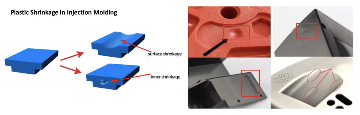
The Physics Behind the Shrinkage
- Thermal Contraction: As the melt cools, molecular kinetic energy decreases, causing molecules to pack closer together.
- Polymer Crystallization: In semi-crystalline plastics, molecules fold into tight, ordered structures, causing massive volume loss.
- Internal Stress Relaxation: Frozen-in stresses from injection pressure release after ejection, altering dimensions.
- Moisture Loss: Insider Secret: Hygroscopic materials (like Nylon) absorb moisture from the air post-molding. As they dry out in the application environment, they undergo additional, often uncalculated, post-molding shrinkage.
(Illustration Concept: Melt → Cooling → Solidification → Final Dimensions showing volume reduction at each stage).
Types of Shrinkage Every Engineer Should Understand
Not all shrinkage happens at the same time or in the same way.
- Volumetric Shrinkage: The total 3D volume reduction of the polymer. (Occurs inside the mold).
- Linear Shrinkage: The 1D reduction in length/width. This is what datasheets publish.
- Mold Shrinkage: The dimensional difference between the mold cavity and the part immediately after ejection.
- Post-Molding Shrinkage: Continued shrinkage occurring 24 to 48 hours after ejection as the part reaches thermal equilibrium.
- Differential Shrinkage: The most critical type. When different areas of the same part shrink at different rates. This is the actual root cause of warpage.
Why Plastic Shrinkage Is Difficult to Predict
Many articles skip this section, but understanding the variables is the key to mastery. Shrinkage is a moving target influenced by four main pillars:
1. Material-Related Variables
Polymer family, filler content, reinforcement (glass/carbon), moisture content, and additive packages (like nucleating agents) all drastically alter shrinkage.
2. Process Variables
Melt temperature, mold temperature, packing pressure, holding time, cooling time, and injection speed. Changing holding pressure by just 10 bar can alter shrinkage by up to 0.2%.
3. Part Design Variables
Wall thickness variations, rib design, bosses, sharp corners, and large flat surfaces.
4. Mold Design Variables
Gate location, runner balance, cooling channel layout, and venting efficiency. Insider Secret: Poor venting traps gas, creating local back-pressure that prevents proper packing, leading to localized high shrinkage that simulation software often misses.
What Causes Excessive Shrinkage
If your parts are coming out undersized, one of these culprits is to blame:
- Insufficient packing pressure: Fails to force extra material into the cavity to compensate for cooling.
- Holding time too short: The gate freezes off before the part is fully packed.
- High melt temperature: Increases the thermal delta (difference between melt and mold temp), leading to higher thermal contraction.
- Uneven mold cooling: Creates differential cooling rates.
- Thick wall sections: The core stays molten longer, shrinking away from the skin (causing sink marks).
- High Crystallinity & Fiber Orientation: Highly crystalline resins shrink more, and fibers restrict shrinkage in the flow direction but allow it in the transverse direction.
Shrinkage Rates of Common Injection Molding Plastics
|
Material |
Typical Shrinkage (%) |
Filled Grade (GF) (%) |
Crystal Structure |
Dimensional Stability |
|
ABS |
0.4 - 0.7 |
0.1 - 0.3 |
Amorphous |
Good |
|
PP |
1.0 - 2.5 |
0.2 - 0.8 |
Semi-Crystalline |
Poor |
|
PE (HDPE/LDPE) |
1.5 - 3.0 |
0.5 - 1.0 |
Semi-Crystalline |
Poor |
|
Nylon (PA6/66) |
0.8 - 1.5 |
0.2 - 0.5 |
Semi-Crystalline |
Fair (Moisture dependent) |
|
PC |
0.5 - 0.7 |
0.1 - 0.2 |
Amorphous |
Excellent |
|
PMMA (Acrylic) |
0.2 - 0.8 |
N/A |
Amorphous |
Excellent |
|
POM (Acetal) |
1.8 - 2.5 |
0.2 - 0.6 |
Semi-Crystalline |
Good |
|
PET / PBT |
1.5 - 2.5 |
0.2 - 0.5 |
Semi-Crystalline |
Good (when filled) |
|
PVC |
0.2 - 0.5 |
N/A |
Amorphous |
Good |
|
TPU / TPE |
1.0 - 2.0 |
N/A |
Amorphous/Elastomeric |
Poor |
|
PPS / PEEK |
0.2 - 0.8 |
0.1 - 0.3 |
Semi-Crystalline |
Excellent |
|
LCP |
0.1 - 0.5 |
0.1 - 0.2 |
Liquid Crystal |
Excellent |
Why PP shrinks much more than ABS:
- PP is semi-crystalline. As it cools, its molecular chains fold tightly into crystalline structures, causing massive volume loss.
- ABS is amorphous; its chains remain tangled like spaghetti, resulting in minimal volume change.
Amorphous vs. Crystalline Plastics: Why Shrinkage Is Completely Different
This is one of the highest-value concepts in injection molding.
Amorphous Polymers (ABS, PC, PMMA)
- Characteristics: Molecules are randomly entangled. They soften gradually over a temperature range.
- Shrinkage Profile: Lower shrinkage (0.2% - 0.8%), highly isotropic (shrinks equally in all directions), and excellent dimensional stability.
Semi-Crystalline Polymers (PP, Nylon, POM, PBT)
- Characteristics: Molecules form highly ordered, tightly packed crystalline regions.
- Shrinkage Profile: Larger shrinkage (1.0% - 3.0%), higher warpage risk.
- Insider Secret: Crystallization is an exothermic process. It releases latent heat. This means a semi-crystalline part actually takes longer to cool than an amorphous part of the exact same thickness, heavily impacting cycle times and shrinkage behavior.
How Glass Fiber (GF) Changes Shrinkage
Adding 30% Glass Fiber (GF) to a resin like PP reduces the overall shrinkage rate from ~2.0% down to ~0.4%. However, it introduces anisotropic (direction-dependent) shrinkage.
- Flow Direction: Fibers align with the melt flow, restricting shrinkage (e.g., 0.2%).
- Cross-Flow Direction: Fibers offer no restriction, allowing higher shrinkage (e.g., 0.8%).
Why warpage sometimes increases with GF: If you mold a large, flat PP+30%GF cover, the massive difference between flow and cross-flow shrinkage will cause the part to warp like a potato chip. Amorphous resins (like PC) handle glass fiber much better regarding flatness.
How Wall Thickness Affects Shrinkage
- Thin Walls (< 1.5mm): Cool almost instantly. High injection pressure is needed, but overall shrinkage is low and uniform.
- Medium Walls (1.5mm - 3.0mm): The sweet spot for most engineering plastics. Balanced cooling and packing.
- Thick Walls (> 3.0mm): The outer skin freezes quickly, but the core remains molten. As the core finally cools and shrinks, it pulls the skin inward, causing sink marks or internal voids.
(Graph Concept: X-axis = Wall Thickness, Y-axis = Shrinkage %. The curve trends upward exponentially after 3mm).
How Gate Location Influences Shrinkage
Gate location dictates how pressure is transmitted through the cavity.
- Center/Hot Runner Gate: Excellent packing efficiency, uniform pressure, lowest shrinkage variation.
- Edge/Fan Gate: Good for flat parts, but pressure drops off at the far end of the flow path.
- Sub/Pin Gate: Used for auto-degating. Warning: These gates are small and freeze off quickly. If holding time isn't perfectly tuned, the gate freezes before the part is packed, resulting in high shrinkage.
How Cooling System Design Controls Shrinkage
Insider Secret: Cooling design contributes up to 70% of a part's dimensional stability, far more than tweaking machine settings.
- Uniform Cooling: Prevents differential shrinkage.
- Conformal Cooling: 3D printed cooling channels that follow the part contour, reducing cycle time and warpage in complex geometries.
- Baffles and Bubblers: Used to cool deep cores and bosses where straight drilled channels can't reach.
- Thermal Balance: The core and cavity must be thermally balanced. If the core is hotter, the part will shrink onto the core and warp upon ejection.
The Relationship Between Shrinkage, Warpage, and Sink Marks
Beginners often confuse these defects. Here is the breakdown:
- Shrinkage: Uniform volumetric reduction. The part is smaller, but still the correct shape.
- Sink Marks: Localized surface shrinkage. Happens when thick sections (like ribs or bosses) pull the outer skin inward.
- Warpage: Bending or twisting caused by differential shrinkage (internal stress).
- Internal Stress: The stored mechanical energy from forced polymer alignment during plastic injection molding.
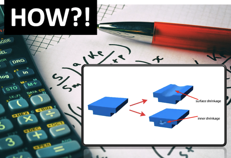
How Mold Designers Calculate Shrinkage Compensation
This is where many make a critical mathematical error.
The Wrong Way: Mold=Part×(1+Shrinkage) The Right Way: Mold=Part/(1?Shrinkage)
Example Calculation: You need a 100 mm part. The material shrinkage is 1.5% (0.015).
- Wrong math: 100×1.015=101.50mm
-
Right math: 100/(1?0.015)=100/0.985=101.522mm
While a 0.022mm difference seems small here, on a 500mm automotive bumper, this mathematical error results in a 0.5mm discrepancy, ruining the assembly!
Best Practice: Always machine the mold "Steel-Safe." Cut the mold slightly smaller than the calculated dimension. It is much easier to cut steel away (making the part larger) than to weld and re-polish steel to make the part smaller.
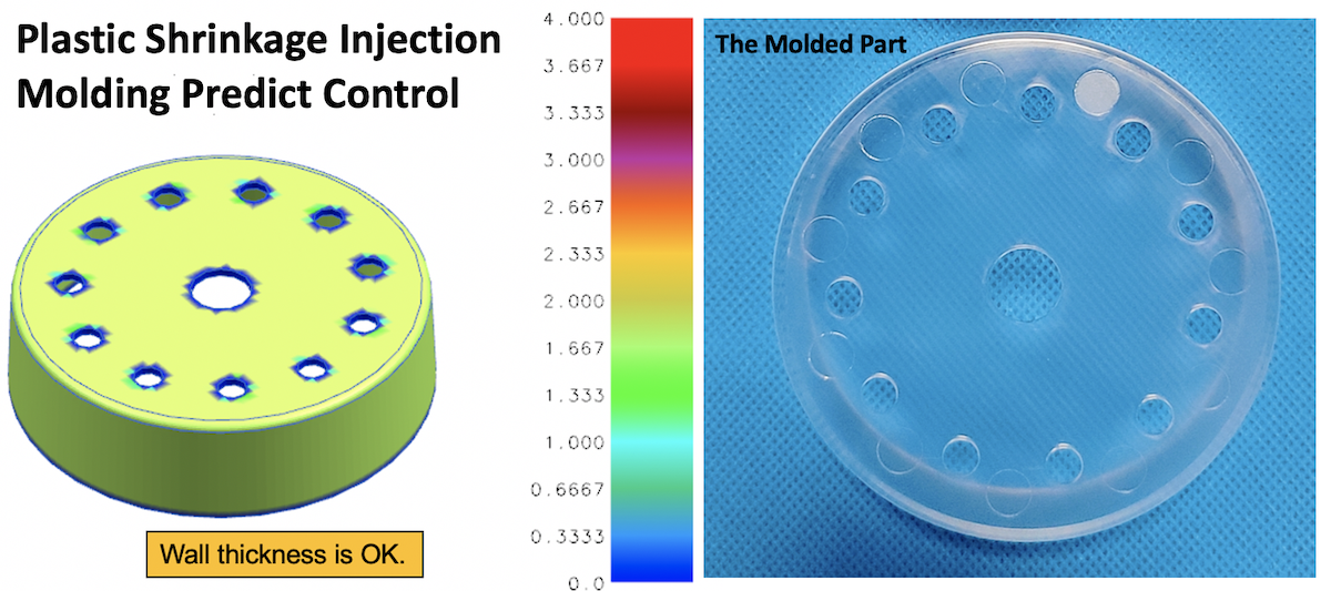
How CAE Simulation Predicts Plastic Shrinkage
Tools like Autodesk Moldflow are industry standards. They run:
- Fill Analysis: Predicts flow fronts and weld lines.
- Packing Analysis: Optimizes holding pressure to minimize volumetric shrinkage.
- Cooling Analysis: Identifies hot spots.
- Warpage Simulation: Calculates final deflection based on differential shrinkage and fiber orientation.
Limitation: Simulation is only as good as the material data card and the input parameters. "Garbage in, garbage out."
How Processing Parameters Affect Shrinkage
|
Parameter |
If Increased... |
Result on Shrinkage |
|
Melt Temperature |
Higher |
Increases(Greater thermal contraction) |
|
Mold Temperature |
Higher |
Increases(Slower cooling, more crystallization) |
|
Packing Pressure |
Higher |
Decreases(Forces more material into cavity) |
|
Holding Time |
Longer |
Decreases(Packs part until gate freezes) |
|
Cooling Time |
Longer |
Decreases(Part stabilizes inside mold) |
|
Injection Speed |
Faster |
Decreases slightly(Higher shear heat, better packing) |
|
Back Pressure |
Higher |
Decreases slightly(Denser melt) |
Practical Methods to Reduce Plastic Shrinkage
1. Improve Part Design
- Maintain uniform wall thickness.
- Use smooth radii for transitions (avoid sharp corners).
- Keep rib thickness at 50-60% of the nominal wall.
2. Optimize Mold Design
- Enlarge gates to delay freeze-off time.
- Implement conformal cooling for complex cores.
- Ensure proper venting to allow complete cavity packing.
3. Optimize Processing
- Increase packing pressure and extend holding time.
- Lower melt and mold temperatures (within material processing windows).
4. Select Better Materials
- Switch to glass-filled or carbon-filled grades.
- Choose amorphous resins (PC, ABS) over semi-crystalline (PP, POM) if tight tolerances are required.
Common Shrinkage Problems and Their Solutions
|
Problem |
Root Cause |
Solution |
|
Part too small |
Insufficient packing / High melt temp |
Increase holding pressure/time; lower melt temp. |
|
Hole diameter incorrect |
Core pin shrinkage / Differential cooling |
Adjust core steel dimensions; add bubblers to core. |
|
Warped housing |
Differential shrinkage / Uneven cooling |
Balance cooling lines; add ribs; change gate location. |
|
Loose snap fit |
Post-molding shrinkage / Creep |
Allow 48hr stabilization; increase local wall thickness. |
|
Large sink marks |
Thick walls / Ribs too thick |
Core out thick sections; reduce rib thickness to 60% of wall. |
Design Guidelines for Minimizing Shrinkage (Checklist)
Before sending your CAD to TEAM Rapid, check these parameters:
- Wall Thickness: Uniform throughout (ideal 1.5mm - 3.0mm).
- Corner Radius: Minimum inside radius = 0.5 x wall thickness.
- Boss Diameter: Outer diameter = 2 x nominal wall; inner hole = standard screw size.
- Rib Thickness: 50% to 60% of the adjoining wall.
- Gate Position: Located at the thickest section of the part.
- Tolerance Allocation: Apply standard commercial tolerances (e.g., SPI standards) unless strictly necessary.
Industry Applications Where Shrinkage Control Is Critical
- Medical Devices: Syringes and diagnostic housings require zero warpage for fluid seals.
- Automotive Parts: Interior trim and dashboards must not warp under high cabin temperatures.
- Precision Gears: Require POM or PEEK. High shrinkage must be perfectly compensated to ensure silent, smooth operation.
- Optical Components: Lenses require ultra-low shrinkage amorphous resins (like COP/COC or Optical PC) to maintain focal lengths.
- Battery Housings: EV battery enclosures require high dimensional stability to maintain crash-safety clearances.
Plastic Shrinkage vs. Thermal Expansion
Many engineers confuse molding shrinkage with the Coefficient of Linear Thermal Expansion (CLTE).
- Plastic Shrinkage: A permanent dimensional change that occurs during the manufacturing phase as the plastic cools from melt to solid.
- Thermal Expansion (CLTE): A reversible dimensional change that occurs in-service as the part heats up and cools down in its operating environment.
Crucial Note: When designing plastic-to-metal assemblies, you must account for both. The plastic will shrink permanently after molding, and then expand/contract at a much higher rate than the metal during daily use.
Frequently Asked Questions (FAQs)
1. Can I completely eliminate plastic shrinkage?
No. All plastics shrink. However, you can minimize it to near-zero (e.g., 0.1%) by using highly filled, amorphous engineering resins like LCP or PEEK, combined with optimized processing.
2. Why did my part shrink more in production than in the prototype?
Prototype molds (often aluminum or soft steel) may have different thermal conductivity than production P20 or H13 steel molds. Additionally, production cycle times are faster, meaning the part is ejected hotter, leading to higher post-molding shrinkage.
3. How long should I wait to measure an injection molded part?
For amorphous plastics, 24 hours is usually sufficient. For semi-crystalline plastics (like Nylon or POM), you should wait 48 hours, as crystallization and moisture absorption/loss continue to alter dimensions.
4. Does regrind (recycled plastic) affect shrinkage?
Yes. Regrund has shorter polymer chains due to thermal degradation during the first melt. This can alter the viscosity and crystallization rate, slightly changing the shrinkage profile. Keep regrind ratios below 20% for tight-tolerance parts.
Ready to Perfect Your Part Design?
Predicting and controlling plastic shrinkage requires a blend of deep material science, precision mold engineering, and advanced processing. Don't leave your part quality to chance.
Partner with the experts at TEAM Rapid. From Moldflow CAE simulation to steel-safe mold machining and scientific injection molding, we ensure your parts meet exact tolerances on the very first shot. Contact us today for a free DFM (Design for Manufacturability) analysis!



 Contact