
Injection Molding for Consumer Electronic: Design & Manufacturing Tips
Injection molding for consumer electronic products is a practical way to produce plastic housings, enclosures, buttons, and internal structural components at production volumes. It provides consistent dimensions and surface finish, while bringing the per-part cost down once tooling is in place. How to do the injection molding design and manufacturing for consumer electronic products? The answer is you requires careful attention to wall thickness, gate design, material selection, and tooling strategy to achieve consistent part quality, tight tolerances, and low per-part cost from prototype through full-scale production.
This guide covers the design choices, material selection, mold architecture, and tooling strategy that have the biggest impact on part quality, production cost, and tooling changes.
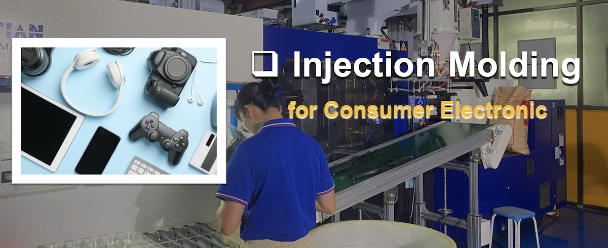
Why Injection Molding Is Widely Used for Consumer Electronic Products
Consumer electronics often require thousands or even millions of identical parts, with controlled tolerances, defined surface finishes, and specific flame-retardancy or environmental requirements. Injection molding can meet these requirements in a single production process. After the mold is built and validated, typical 15–45 second shot cycles make the process economical for mid- to high-volume production.
Plastic injection molding also handles geometries that would be difficult or costly to produce by machining or additive manufacturing. Snap fits, living hinges, internal ribs, boss features, and thin-wall sections can often be molded in one shot without secondary machining. For engineering teams balancing unit cost, appearance, and structural performance, that combination makes injection molding a common choice.
What Types of Consumer Electronic Parts Are Injection Molded?
Injection molded consumer electronic components cover both cosmetic and structural applications. Common examples include:
- Smartphone and tablet back covers, mid-frames, and SIM trays
- Remote control housings and button pads
- Charger and power adapter shells
- Smart-home device enclosures (speakers, sensors, hubs)
- Wearable electronics housings (earbuds, watch cases, fitness tracker bodies)
- Audio product grilles and headphone shells
- Internal brackets, connector housings, and PCB mounting clips
The priorities vary by application. A smartphone back cover may require a Class-A surface finish and tight control of mating features. An internal bracket may care more about dimensional stability and screw-holding strength than appearance. Defining those requirements early helps avoid unnecessary mold changes later.
Injection Molding vs. CNC Machining and 3D Printing
|
Factor |
Injection Molding |
CNC Machining |
3D Printing |
|
Economical volume |
500+ parts |
1–50 parts |
1–20 parts |
|
Per-part cost at volume |
Very low |
High |
High |
|
Tooling investment |
2,000– 50,000+ |
None |
None |
|
Dimensional consistency |
±0.1–0.2mm typical |
±0.01–0.05 mm |
±0.1–0.3 mm |
|
Surface finish |
Mold texture/polish directly |
Post-processing needed |
Layer lines visible |
|
Material options |
Broad (ABS, PC, PA, PBT, TPU) |
Broad |
Limited |
|
Lead time to first part |
3–8 weeks |
Days |
Hours–days |
CNC machining works well for functional prototypes and bridge quantities when production tooling is not yet justified. 3D printing is useful for concept models and early fit checks. Neither process provides the same combination of surface consistency, material options, and unit economics that injection molding offers at production volumes.
Mold Design for Consumer Electronic Components
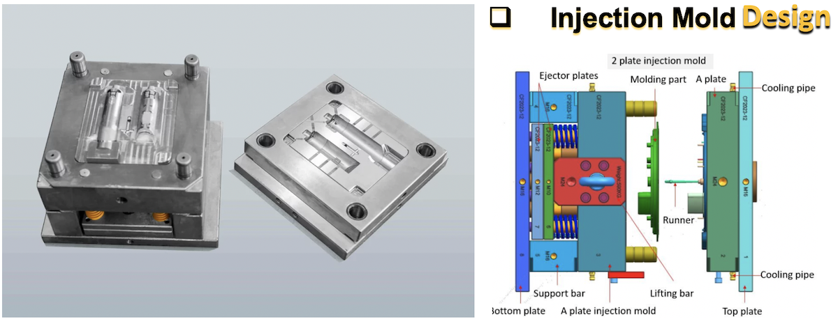
Mold architecture has a direct effect on part quality, cycle time, tooling cost, and production stability. A well-designed mold produces consistent parts with controlled scrap rates. Poor mold design can lead to flash, sink marks, warpage, and dimensional drift from the start of production.
Key mold design considerations for consumer electronics include cooling layout, ejection strategy, surface treatment, and steel grade. Cooling accounts for 60–70% of total cycle time, so conformal cooling channels or baffles positioned close to the cavity surface are important for thin-wall electronic housings. Ejection also needs to be planned around cosmetic surfaces. Stripper plates, sleeve ejectors, or air-assist ejection can help keep visible pin marks off those surfaces.
Specify the mold surface finish early using SPI or VDI standards. SPI A-1 through A-3 covers diamond-polished glossy surfaces, while SPI B and C grades cover semi-gloss and matte finishes. VDI/MT textures can provide custom patterns for grip or visual differentiation. Because texture depth affects the required draft angle, these two requirements should be coordinated during mold design.
Material selection also affects mold design. Common resins for consumer electronics include:
- ABS – Good impact strength and easy to paint or plate, making it suitable for remote controls and charger housings. HDT approximately70°C- 80°Cwhen standard unannealed ABS under a 1.80 MPA
- PC (Polycarbonate) – High impact resistance and heat resistance (At 0.45 MPA, it is typically 140 °C to 145°C. Stating ~130°C is on the lower end/inaccurate for standard neat Polycarbonate.). Commonly used for transparent covers, LED lenses, and high-temperature enclosures.
- PC/ABS blends – A balance of heat resistance and processability. UL 94 V-0 flame-retardant grades are available for applications such as laptop housings and set-top boxes.
- PP (Polypropylene) – Low cost with excellent fatigue life for living hinges and snap-fit clips. Paint adhesion is limited.
Specify flame-retardancy requirements (UL 94 V-0, V-1, or HB) during material selection. FR additives can affect flow length, color consistency, and mechanical properties. Confirm the processing parameters with your molder before the resin grade is finalized.
Thin-Wall Injection Molding
Many consumer electronic housings use wall thicknesses of 0.8 mm to 1.5 mm to reduce weight and material use. Filling these sections requires higher injection pressure, faster injection speed, and tighter melt-temperature control than standard molding.
Challenges specific to thin-wall molding include:
- Short shots and hesitation marks if injection speed is insufficient or venting is inadequate.
- Dimensional sensitivity to process variation. Small changes in melt temperature or packing pressure can cause measurable size shifts.
- Higher clamp-force requirements due to elevated injection pressures.
- Gate and runner sizing becomes critical. Undersized gates cause excessive pressure drop; oversized gates leave visible vestiges on cosmetic surfaces.
To reduce these risks, specify high-flow resin grades intended for thin-wall applications. Run mold flow simulation before cutting steel to identify fill imbalances, air traps, and potential weld-line locations. Also confirm that the molding machine can provide the required injection rate, typically >300 mm/s for walls below 1.0 mm.
Gate Location and Flow Direction
Gate position is one of the most important decisions in injection mold design for consumer electronics. It determines how molten plastic enters the cavity and, in turn, affects weld-line location, packing efficiency, cosmetic appearance, and dimensional stability.
Gate type selection
- Edge gates – Simple and low cost, but they leave a visible vestige. Suitable for non-cosmetic internal parts.
- Submarine (tunnel) gates – Hide the vestige below the parting line. Common for cosmetic housings where a visible gate mark is not acceptable.
- Pin-point gate – A small round gate (typically 0.5–1.5 mm diameter) that enters from the top or bottom of the part. Common in three-plate molds and hot-runner systems. Ideal for small consumer electronic components like earbud shells, SIM trays, and connector covers. Leaves a minimal vestige that is easily concealed.
-
Fan gate – A wide, thin gate that spreads the melt front across the full width of the cavity. Reduces jetting and flow marks on flat, wide parts such as tablet back covers, panel bezels, and charger faceplates. Requires more trimming but delivers superior surface uniformity.
-
Tab gate – A small rectangular tab extends from the part edge, and the gate feeds into the tab rather than directly into the cavity. This eliminates jetting and reduces flow marks on Class-A surfaces. Frequently specified for glossy smartphone bezels, smart-home device faceplates, and any part where direct gate impingement would cause cosmetic defects.
-
Diaphragm gate – A ring-shaped gate around the entire perimeter of a round or cylindrical part. Produces uniform, concentric filling with minimal warpage. Used for cylindrical speaker housings, lens barrels, and round sensor covers.
-
Direct (sprue) gate – The largest gate type, connecting the sprue directly to the part. Provides the lowest pressure drop and fastest filling but leaves a prominent vestige requiring post-mold trimming. Rarely used for cosmetic consumer electronics parts; more common for large single-cavity internal components.
-
Hot-runner valve gates – Eliminate cold runners, provide precise gate freeze-off control, and reduce material waste. Preferred for multi-cavity production molds and parts with strict cosmetic requirements.
How to Choose the Right Gate Type
Part characteristic
Recommended gate type
Small cosmetic housing (<50 mm)
Pin-point or submarine
Flat, wide cover or panel
Fan or tab gate
Cylindrical or round part
Diaphragm gate
High-volume multi-cavity production
Hot-runner valve gate
Internal non-cosmetic bracket
Edge or direct gate
Glossy Class-A surface
Tab gate or valve gate
Flow direction effects
Gate location determines flow direction, which affects molecular orientation and shrinkage anisotropy. With glass-filled materials, fibers tend to align with the flow direction. That alignment can create different shrinkage rates in the flow and transverse directions, which may contribute to warpage. Symmetric gate placement can help balance shrinkage across the part.
For multi-cavity molds, the runner system should be balanced so the cavities fill at the same time. Unbalanced filling can create part-to-part variation that process adjustments alone may not eliminate. Confirm gate locations and runner balance with the mold designer during the DFM review, before tool fabrication begins.
Tooling Strategy: Prototype, Bridge, or Production Mold
Selecting the tooling approach depends on the development stage, budget, and target volume. Moving straight to hardened production tooling before the design has been validated can be one of the more expensive mistakes in consumer electronics development.
Prototype tooling (rapid tooling)
- Aluminum or soft steel (P20, NAK80) molds
- 5,000–10,000 shot life
- Lead time: 5–15 business days
- Best for: design validation, fit testing, functional samples, market research
Use rapid tooling for injection molded parts when you need functional prototypes in production-intent materials without taking on the full cost of production tooling. It gives the team a chance to check snap-fit engagement, assembly tolerances, and cosmetic appearance before investing in hardened production steel.
Bridge tooling
- Pre-hardened steel (P20, 718H) molds, 1–4 cavities
- 5,000–100,000 shot life
- Lead time: 3–5 weeks
- Best for: pilot runs, market testing, and early customer deliveries while the production tool is being built
Production tooling
- Hardened steel (H13, S136, 420SS) molds
- 1,000,000+ shot life
- Multi-cavity layouts (4, 8, 16+ cavities) with hot-runner systems
- Lead time: 6–12 weeks depending on complexity
- Best for: high-volume manufacturing with tight tolerances and cosmetic requirements
Decision framework
|
Question |
Prototype |
Bridge |
Production |
|
Volume needed? |
<5,000 |
5,000–100,000 |
>100,000 |
|
Design finalized? |
No |
Partially |
Yes |
|
Budget available? |
Low |
Medium |
High |
|
Cosmetic finish critical? |
No |
Maybe |
Yes |
Complete at least one DFM review and one prototype validation cycle before committing to production tooling. Once hardened steel has been cut, design changes become more expensive and take more time.
How to Choose an Injection Molding Manufacturer for Consumer Electronics
Selecting the right manufacturing partner matters as much as the part design. A capable molder can reduce risk from the first prototype through sustained production.
-
DFM capability
A qualified supplier should provide a detailed DFM report before quoting, with attention to wall thickness, draft angles, gate location, ejection, and potential molding defects. If a molder provides a quote without asking engineering questions, that is a reason to look more closely at its process.
-
Material traceability and compliance
Request material certifications (COA, UL yellow card) for every resin lot. This is especially important for flame-retardant grades used in electronics that must comply with UL, CE, or RoHS requirements. Confirm that the supplier has documented procedures for material handling and storage.
-
Engineering change response
Consumer electronic products often go through several design iterations. Your molder should have a clear ECN (Engineering Change Notice) process covering impact assessment, cost quotation, and schedule communication. Ask how mid-production design changes are handled and how long mold modifications typically take.
-
Quality control systems
Evaluate the supplier's inspection capability:
- First Article Inspection (FAI) with a full dimensional report
- In-process SPC monitoring of critical parameters (melt temperature, injection pressure, cycle time)
- Cosmetic inspection under controlled lighting (D65 illuminant, 1,000 lux minimum)
- AQL sampling per ISO 2859 or equivalent
- Automated vision inspection for high-volume critical features
-
Production scalability
Confirm that the supplier can scale from prototype quantities to full production without moving the molds to another facility. Ask about available machine tonnage, cavity-count options, and secondary operations such as ultrasonic welding, painting, pad printing, and assembly.
For teams seeking one partner from prototype through production, explore custom plastic injection molding services that cover rapid tooling, low-volume runs, and full-scale manufacturing under one roof.
Conclusion
Injection molding for consumer electronic products is a mature, well-established process, but good results still depend on decisions made early in the project. Wall thickness, gate placement, material selection, and tooling strategy all affect part quality, cosmetic appearance, and total program cost. Addressing these issues before steel is cut can reduce mold revisions and help keep the production schedule on track.

If you are developing a consumer electronic product and need a manufacturing partner that understands both the engineering and cosmetic requirements, contact TEAM Rapid to request a free DFM review and quote. Our team supports projects from single-cavity prototype molds through multi-cavity production tooling, with clear communication throughout the process. Contact us today!


 Contact