
From Prototype to Production: A Complete Manufacturing Roadmap
A prototype to production manufacturing roadmap is a step-by-step guide that helps engineers and product teams move from prototype to mass production by covering DFM analysis, manufacturing process selection, tooling strategy, first article inspection, and pilot production—ensuring a smooth, cost-effective transition from a working prototype to repeatable, high-quality production parts.
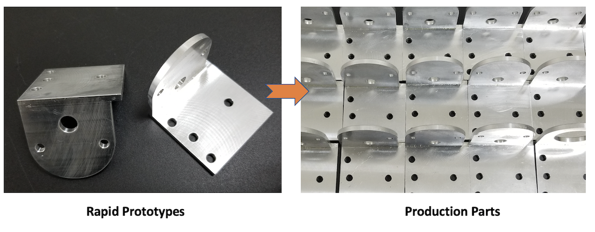
From Prototype to Production: What Actually Changes
A working prototype is an exciting milestone—but it is not automatically production-ready. Many product teams discover this the hard way, only after investing in tooling that produces parts with unexpected defects, or after realizing that the per-unit cost at volume is far higher than anticipated.
Prototype objectives vs. production objectives are fundamentally different. A prototype exists to answer questions: Does the concept work? Does it fit? Does it look right? Production, on the other hand, must answer a different set of questions: Can this part be made consistently? Can it be made economically? Can it be made thousands or millions of times without variation?
The Three Major Challenges When Scaling
Design manufacturability. A geometry that works beautifully in a CNC-machined prototype may be impossible—or prohibitively expensive—to injection mold. Undercuts, thin walls, sharp internal corners, and complex draft requirements can all create problems that never appeared during prototyping.
Process repeatability. A skilled machinist can produce one perfect part. But can the process produce 10,000 identical parts? Repeatability requires stable tooling, controlled process parameters, and a manufacturing system designed for consistency.
Cost at volume. Prototype processes like 3D printing or CNC machining have high per-unit costs but low setup costs. Production processes like injection molding have high setup costs (tooling) but very low per-unit costs. Understanding the crossover point is essential.
Why Decisions Made During Prototyping Determine Production Cost
Every design decision made during prototyping carries forward into production. Wall thickness, material selection, tolerance requirements, surface finish expectations—these all directly affect tooling complexity, cycle time, scrap rate, and ultimately, the cost per part.
Prototype DFM vs. Production DFM are not the same thing. During prototyping, you might accept a design that requires five-axis CNC machining because you only need ten parts. In production, that same geometry might require complex side-actions in a mold, increasing tooling cost by 40% and cycle time by 30%.
Deep insight: A prototype proves that the product can work. Production must prove that the product can be made consistently, economically, and repeatedly.
The Complete Prototype-to-Production Manufacturing Roadmap
Before diving into individual stages, here is the complete roadmap from concept to mass production:
Concept→Prototype→Functional Validation→DFM→Process Selection→Tooling→First Article→Pilot Production→Production Validation→Mass Production→Continuous Improvement
At every stage, there is a decision gate—a question that must be answered before moving forward.
|
Stage |
Main Question |
Typical Output |
Decision |
|
Prototype |
Does the design work? |
Prototype parts |
Continue / redesign |
|
DFM |
Can it be manufactured efficiently? |
DFM report |
Modify / release |
|
Process Selection |
Which process fits volume and requirements? |
Manufacturing plan |
Select process |
|
Tooling |
Can production tooling be built? |
Mold / tool |
Trial |
|
First Article |
Does the tool produce acceptable parts? |
FAI / T1 samples |
Approve / correct |
|
Pilot Run |
Is the process repeatable? |
Pilot batch |
Release / improve |
|
Production |
Can we make it consistently? |
Production parts |
Scale |
Skipping or rushing any of these stages is one of the most common reasons products fail in production—or arrive late and over budget.
Stage 1: Define the Product Requirements Before Manufacturing
Start with the Functional Requirements
Before any manufacturing process is selected, the product's functional requirements must be clearly defined:
- Load and strength – What forces will the part experience in service?
- Temperature – What is the operating temperature range?
- Chemical exposure – Will the part contact solvents, oils, or cleaning agents?
- Environmental conditions – UV exposure, humidity, outdoor use?
- Expected service life – Is this a disposable product or a 10-year component?
- Assembly requirements – How does this part connect to other components?
These requirements directly influence material selection, manufacturing process, and tolerance strategy.
Separate Critical Dimensions from Non-Critical Dimensions
Not every dimension on a drawing is equally important. Ask:
- Which dimensions actually affect function?
- Which dimensions are cosmetic or nominal?
Applying unnecessarily tight tolerances to non-critical features is one of the most common ways to inflate manufacturing cost. A ±0.01mm tolerance on a cosmetic surface that has no functional impact adds cost without adding value.
Create a Controlled Product Definition
A complete product definition should include:
- 3D CAD model (current revision)
- 2D drawings with critical dimensions identified
- Material specification (grade, supplier if applicable)
- Surface finish requirements
- Color and appearance standards
- Tolerances and GD&T callouts
- Cosmetic requirements (texture, gloss, acceptable defects)
- Testing requirements (functional, environmental, regulatory)
Why Revision Control Matters
Deep insight: One of the most expensive manufacturing mistakes is building tooling from an outdated CAD revision.
When multiple teams are working on a design simultaneously, version confusion is common. A mold built from Revision C when the design has already moved to Revision E means expensive tool modifications—or in the worst case, a completely new mold.
Stage 2: Build and Validate the Prototype
Choosing the Right Prototype Manufacturing Process
Different prototype processes serve different purposes:
|
Process |
Best For |
Limitations |
|
3D Printing |
Fast form/fit checks, complex geometry |
Limited material properties, poor surface finish |
|
CNC Machining |
Functional testing, tight tolerances, real materials |
Higher cost, geometry limitations |
|
Vacuum Casting |
Small batches of urethane parts, appearance models |
Limited material range, short tool life |
|
Sheet Metal Prototyping |
Enclosures, brackets, structural parts |
Limited to sheet metal geometries |
|
Prototype Injection Molding |
Testing actual production behavior |
Higher upfront cost, longer lead time |
At TEAM Rapid, we help customers select the most appropriate prototyping method based on what questions they need to answer—not simply what is fastest or cheapest.
What Should You Validate with a Prototype
- Form – Does the shape match the design intent?
- Fit – Does it assemble correctly with mating parts?
- Function – Does it perform its intended role under expected conditions?
- Assembly – Can it be assembled and disassembled as required?
- Ergonomics – Is it comfortable and intuitive to use?
- Appearance – Does it look acceptable to the end user?
- Basic mechanical performance – Does it survive expected loads?
What Prototypes Cannot Tell You
This is a critical section that many teams overlook. A 3D-printed or CNC-machined prototype may not accurately predict:
- Injection molding shrinkage – Different materials shrink at different rates, affecting final dimensions
- Weld lines – Where flow fronts meet during molding, creating potential weak points
- Sink marks – Surface depressions over thick sections
- Warpage – Distortion due to uneven cooling or shrinkage
- Gate appearance – The visible mark where material enters the cavity
- Ejection behavior – Whether the part releases cleanly from the mold
- Production cycle time – How long each part takes to produce
- Production tooling cost – The actual investment required for molds or dies
When Should You Build Another Prototype Instead of Moving to Tooling
Deep insight: Don't ask "Is the prototype finished?" Ask "Have we answered all the questions that could make production fail?"
If there are unresolved questions about fit, function, or assembly, building another prototype is almost always cheaper than modifying production tooling later.
Stage 3: Design for Manufacturing (DFM)
DFM is where the transition from prototype to production either succeeds or fails. It is the stage where engineering expertise delivers the highest return on investment.
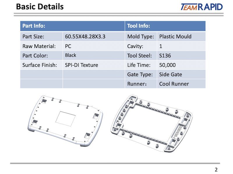
What Is DFM and Why Does It Matter
Design for Manufacturing is the systematic process of optimizing a product design so that it can be manufactured efficiently, reliably, and at the lowest possible cost—without compromising function.
DFM is not about simplifying the design until it no longer works. It is about understanding the constraints and capabilities of the chosen manufacturing process and designing within them.
Injection Molding DFM Considerations
Injection molding is the most common production process for plastic parts, and it has the most extensive DFM requirements:
- Wall thickness – Uniform wall thickness prevents sink marks, warpage, and incomplete filling. Typical range: 1.5–4mm depending on material.
- Draft angle – Every surface parallel to the mold opening direction needs draft (typically 1–3°) for part ejection.
- Ribs – Ribs add stiffness without increasing wall thickness, but must be designed correctly (typically 60–70% of nominal wall thickness) to avoid sink marks.
- Bosses – Cylindrical features for screws or assembly need proper design to avoid sink and ensure strength.
- Undercuts – Features that prevent straightforward mold opening require side-actions, lifters, or collapsible cores—adding cost and complexity.
- Parting lines – The line where mold halves meet. Its location affects appearance, flash, and tool complexity.
- Gates – The entry point for molten plastic. Gate type and location affect appearance, weld line position, and packing.
- Ejector locations – Ejector pins leave marks. Their placement must balance ejection force with cosmetic requirements.
- Sink marks – Surface depressions caused by material shrinkage, typically over thick sections or ribs.
- Weld lines – Lines formed where flow fronts meet. They can be structural weak points and cosmetic defects.
- Warpage – Distortion caused by differential shrinkage. Material selection, wall thickness uniformity, and gate design all influence warpage.
- Venting – Trapped air must escape the cavity. Poor venting causes burns, short shots, and surface defects.
- Cooling – Uniform cooling is essential for dimensional stability and cycle time.
CNC Machining DFM Considerations
- Tool accessibility – Can the cutting tool reach all required surfaces?
- Deep cavities – Deep pockets require long tools, which deflect and limit achievable tolerances.
- Internal corners – End mills are round. Sharp internal corners are impossible without special processes.
- Fixturing – How will the part be held during machining? Complex fixturing adds cost.
- Tolerances – Tighter tolerances require slower machining, more setups, and more inspection.
- Machining time – Every additional feature adds time. Simplifying geometry reduces cost.
Die Casting DFM Considerations
- Wall thickness – Typically 1.5–5mm for aluminum die casting.
- Draft – Required for ejection, typically 1–3°.
- Parting line – Affects flash and cosmetic appearance.
- Porosity – Inherent to die casting. Must be considered for pressure-tight or structural applications.
- Ejection – Ejector pin marks and their placement.
- Machining allowance – Areas requiring post-casting machining need additional material.
DFM Questions That Should Be Answered Before Tooling
Before any steel is cut, these questions must have clear answers:
- Can the part be removed from the mold?
- Are the tolerances realistic for the chosen process?
- Is the wall thickness suitable?
- Will the gate create a cosmetic problem?
- Where will weld lines appear, and are they acceptable?
- Could ribs cause sink marks?
- Is the current material suitable for the production process?
- Are there undercuts that require additional mold complexity?
- Is the parting line location acceptable?
Why Fixing a Design Problem Before Tooling Is Cheaper
The cost of change escalates dramatically as you move through the manufacturing process:
CAD change→Prototype change→Tooling change→Production change
A design modification in CAD costs hours of engineering time. The same modification after tooling has been built can cost thousands of dollars in mold modifications—and weeks of delay. After production has started, the cost includes scrap, rework, and potential customer impact.
At TEAM Rapid, our DFM process is designed to identify and resolve these issues before any steel is cut. Our engineers review every design for manufacturability, providing detailed DFM reports that highlight potential problems and recommend solutions—ensuring that when tooling begins, the design is truly production-ready.
Stage 4: Choose the Right Manufacturing Process
CNC Machining vs. Injection Molding
CNC machining excels at low volumes, tight tolerances, and complex geometries in metals and engineering plastics. Injection molding excels at high volumes of plastic parts with excellent repeatability and low per-unit cost. The crossover point typically falls between 100 and 1,000 parts, depending on part complexity and material.
3D Printing vs. CNC Machining
3D printing offers unmatched speed and geometric freedom but limited material properties and surface finish. CNC machining provides superior mechanical properties, tighter tolerances, and better surface finish—but at higher cost and with geometry limitations.
CNC Machining vs. Die Casting
For metal parts, CNC machining offers flexibility and precision at low volumes. Die casting offers lower per-unit cost at higher volumes but requires significant tooling investment and has limitations on wall thickness and internal features.
Injection Molding vs. 3D Printing
For plastic parts at production volumes, injection molding is almost always more economical. 3D printing remains relevant for prototyping, bridge production, and highly customized parts.
When Is Low-Volume Manufacturing Better Than Mass Production
Not every product needs mass production. If your annual volume is below 5,000–10,000 units, low-volume manufacturing methods like rapid tooling, CNC machining, or vacuum casting may be more cost-effective than investing in full production tooling.
The Four Factors That Determine Process Selection
- Part geometry – Complexity, size, undercuts, wall thickness
- Material – Metal, plastic, elastomer; specific grade requirements
- Quantity – Annual volume and product lifecycle
- Target cost – Per-unit cost target and total program budget
Why the Cheapest Prototype Process May Not Be the Cheapest Production Process
Deep insight: Manufacturing process selection should be based on total cost at production volume—not on the cost of making one part.
A part that costs 50 to CNC machine might cost 0.80 to injection mold—but only after a $15,000 mold investment. At 100 parts, CNC is cheaper. At 50,000 parts, injection molding saves tens of thousands of dollars.
Stage 5: Tooling, First Article, and Production Validation
Tooling Strategy
Once the manufacturing process is selected and DFM is complete, tooling begins. At TEAM Rapid, we offer a range of tooling options:
- Rapid tooling – Aluminum or soft steel molds for bridge production and market testing (hundreds to low thousands of parts)
- Production tooling – Hardened steel molds for high-volume production (hundreds of thousands to millions of parts)
- Multi-cavity tooling – For maximum output at lowest per-unit cost
The right tooling strategy depends on your volume requirements, budget, and timeline.
First Article Inspection (FAI)
The first parts produced from new tooling (T1 samples) must be thoroughly inspected against the product definition. This includes:
- Dimensional inspection against 2D drawings
- Material verification
- Functional testing
- Cosmetic evaluation
- Assembly testing with mating parts
First article approval is the gate between tooling and production. Rushing this stage leads to quality problems that multiply across thousands of parts.
Pilot Production
A pilot run (typically 100–500 parts) validates that the process is repeatable and stable. During pilot production, the team monitors:
- Dimensional consistency across the batch
- Cycle time stability
- Scrap rate
- Process parameter sensitivity
- Packaging and handling requirements
Production Validation and Scale-Up
Once pilot production confirms process stability, full production can begin. Production validation includes:
- Statistical process control (SPC)
- Ongoing dimensional monitoring
- Regular quality audits
- Supply chain readiness confirmation
How TEAM Rapid Supports Your Prototype-to-Production Journey
At TEAM Rapid, we understand that the journey from prototype to production is not a simple linear process—it requires engineering judgment, process expertise, and careful decision-making at every stage. Our services cover the complete roadmap:
- Rapid prototyping – CNC machining, 3D printing, vacuum casting, and sheet metal fabrication
- DFM analysis – Detailed manufacturability review before tooling begins
- Rapid tooling and production tooling – From aluminum bridge molds to hardened steel production molds
- Injection molding – From pilot runs to mass production
- CNC machining – Low-volume production parts in metals and plastics
- Quality assurance – FAI, dimensional inspection, and ongoing quality control
We work with engineers, product developers, startups, and OEMs worldwide to help them make the right decisions at each stage—avoiding expensive mistakes and accelerating time to market.
Conclusion: The Key to Successful Production Is Preparation
The difference between a smooth production launch and an expensive, delayed one almost always comes down to preparation. Teams that invest time in proper DFM, process selection, and validation before tooling begins consistently achieve better results—faster, cheaper, and with fewer surprises.
If you are moving a product from prototype toward production and want expert guidance on DFM, process selection, or tooling strategy, contact TEAM Rapid for a free consultation. Our engineering team will help you identify the most efficient path from where you are today to reliable, cost-effective production. Contact us today!


 Contact