
3D Printing vs. Injection Molding for Functional Parts: A Complete Engineering Guide
When comparing 3D printing vs injection molding for functional parts, 3D printing is best suited for low-volume prototyping and end-use parts under 200 units, while injection molding offers superior strength, fatigue resistance, and per-part cost efficiency at production volumes above 500 units—making the most effective manufacturing strategy a staged approach that transitions from 3D printed functional prototypes to rapid tooling and low-volume injection molding as your design matures and production quantity increases.
Many peoples believes that 3D printing is for prototypes, injection molding is for mass production. But for engineers, product developers, startups, and sourcing managers making real manufacturing decisions, this answer falls dangerously short.
The real questions you need answered are:
- Can 3D printed parts actually serve as functional end-use components?
- How do strength, durability, heat resistance, and fatigue performance truly compare?
- At what production volume does switching to injection molding make financial sense?
- How do material properties differ—not just material names, but actual mechanical behavior?
- What hidden costs affect the real manufacturing decision?
- Can companies strategically use both processes in the same product development workflow?
This guide answers all of these questions with engineering-level depth, real-world examples, and a practical decision framework. Whether you're developing a consumer product, an industrial component, or a medical device, this article will help you choose the right manufacturing process—or the right combination of processes—for your specific application.
Can 3D Printed Parts Really Be Used as Functional End-Use Parts
The short answer is: yes, but with significant caveats.
Modern additive manufacturing has advanced far beyond simple visual prototypes. Technologies like Selective Laser Sintering (SLS), Multi Jet Fusion (MJF), and Fused Deposition Modeling (FDM) with engineering-grade thermoplastics can produce parts that withstand real mechanical loads, chemical exposure, and thermal cycling.
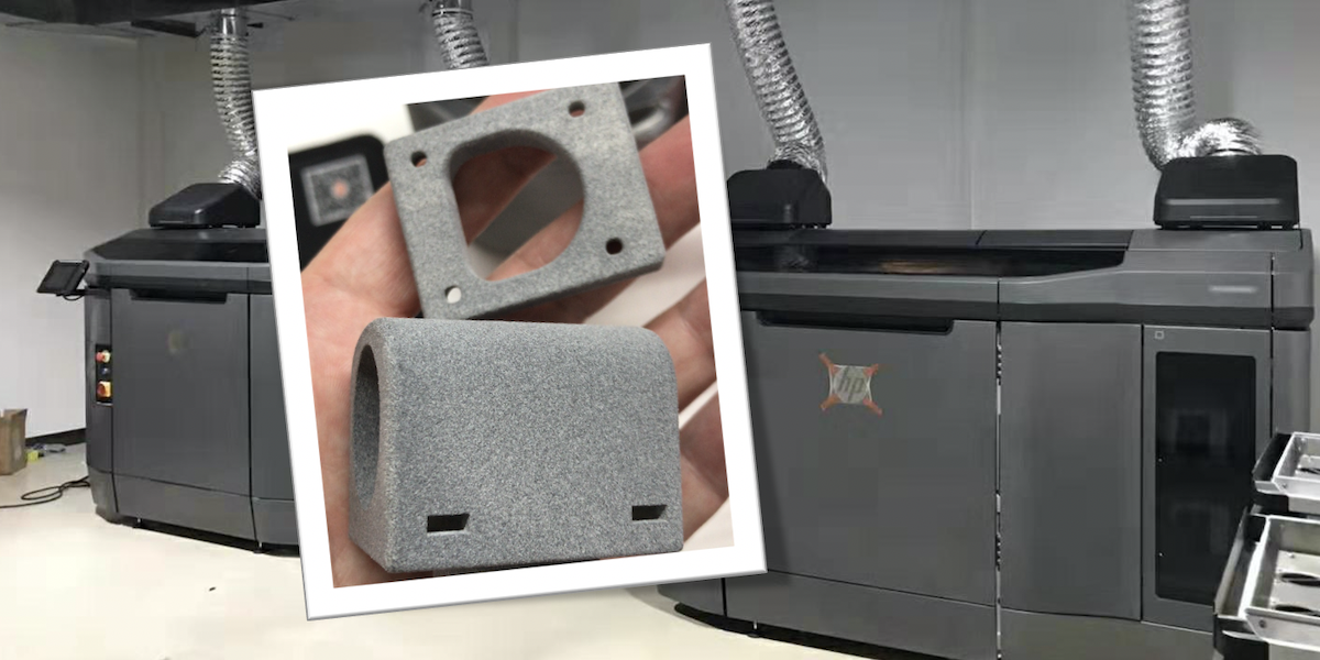
When 3D Printing Works for Functional Parts
|
Application |
Suitable 3D Printing Process |
Typical Material |
|
Housings and enclosures |
SLS / MJF |
Nylon 12, Nylon 11 |
|
Ducts and manifolds |
SLS |
Nylon, TPU |
|
Jigs and fixtures |
FDM |
PC, ASA, Carbon-fiber nylon |
|
Low-stress brackets |
MJF |
Nylon 12 |
|
Custom tooling inserts |
Metal 3D Printing (SLM/DMLS) |
Stainless steel, Aluminum |
When 3D Printing Falls Short
However, 3D printed parts still face limitations that engineers must account for:
- Anisotropic strength: FDM parts are significantly weaker along the layer direction (Z-axis), often 40–60% weaker than in-plane strength.
- Surface finish: Layer lines create stress concentration points and can trap contaminants in food-grade or medical applications.
- Creep and fatigue: Most polymers used in 3D printing exhibit higher creep rates than their injection-molded counterparts due to lower crystallinity and internal voids.
- Dimensional stability: Warpage and shrinkage variation can make tight tolerances (±0.05 mm) difficult to achieve consistently.
Key takeaway: 3D printing is viable for functional parts in low-volume, low-stress, or highly customized applications. For high-cycle fatigue, tight tolerances, or high-volume production, injection molding remains the superior choice.
Material Properties: Why Material Names Alone Don't Tell the Full Story
A common mistake in manufacturing decisions is comparing materials by name alone. "Nylon 12 is Nylon 12, right?" Wrong. The same base polymer behaves very differently depending on the manufacturing process.
Nylon 12: SLS vs. Injection Molding
|
Property |
SLS Nylon 12 |
Injection Molded Nylon 12 |
|
Tensile Strength |
48–52 MPa |
60–75 MPa |
|
Elongation at Break |
15–25% |
30–50% |
|
Flexural Modulus |
1,500–1,800 MPa |
2,000–2,800 MPa |
|
Heat Deflection Temp |
140–150°C |
150–180°C |
|
Density |
0.95–1.05 g/cm³ |
1.01–1.04 g/cm³ |
|
Internal Porosity |
2–8% |
Near 0% |
The injection-molded part achieves higher density, better molecular alignment, and superior mechanical properties because the material is fully melted, packed under high pressure, and cooled in a controlled manner.
ABS: FDM vs. Injection Molding
|
Property |
FDM ABS |
Injection Molded ABS |
|
Tensile Strength (X-Y) |
25–35 MPa |
40–50 MPa |
|
Tensile Strength (Z) |
10–18 MPa |
40–50 MPa |
|
Impact Strength |
30–60% of molded |
Reference (100%) |
|
Surface Quality |
Visible layer lines |
Smooth, Class A possible |
Engineering implication: If your part experiences multi-directional loading or impact events, injection molding provides significantly more predictable and reliable performance.
Strength, Durability, Heat Resistance, and Fatigue: A Real-World Comparison
Strength
For static loads, 3D printed parts can often meet requirements at low volumes. However, the directionality of strength in FDM and the porosity in SLS mean that safety factors must be increased by 2–3x compared to injection-molded equivalents.
Durability and Fatigue Life
This is where the gap widens dramatically. Injection-molded parts benefit from:
- Uniform molecular structure
- No internal voids or layer boundaries
- Consistent fiber orientation (in glass-filled materials)
In fatigue testing, injection-molded glass-filled nylon typically achieves 5–10x longer fatigue life than SLS nylon under identical cyclic loading conditions.
Heat Resistance
Heat Deflection Temperature (HDT) values for 3D printed parts are typically 10–30°C lower than injection-molded equivalents of the same material. This matters enormously for under-hood automotive parts, electronic enclosures near heat sources, or any application approaching the material's thermal limits.
Chemical Resistance
Layer boundaries in 3D printed parts create pathways for chemical ingress. Injection-molded parts, being fully dense, offer superior resistance to solvents, fuels, and cleaning agents.
Hidden Costs That Affect the Real Manufacturing Decision
Most cost comparisons focus on per-part price. But smart engineers and sourcing managers look at Total Cost of Ownership (TCO):
|
Cost Factor |
3D Printing |
Injection Molding |
|
Tooling cost |
$0 |
2,000– 50,000+ |
|
Per-part cost (1–100 units) |
5– 50 |
Not practical |
|
Per-part cost (1,000+ units) |
5– 50 (unchanged) |
0.50– 5.00 |
|
Post-processing |
Often required |
Minimal |
|
Scrap rate |
1–5% |
1–3% |
|
Design change cost |
Low (reprint) |
High (modify mold) |
|
Lead time for changes |
1–3 days |
2–6 weeks |
|
Quality consistency |
Batch-dependent |
Highly repeatable |
|
Certification/testing |
May require re-validation |
Stable process |
The breakeven point typically falls between 200 and 2,000 units, depending on part complexity, size, and material. Below this range, 3D printing is usually more economical. Above it, injection molding delivers dramatically lower per-part costs and superior quality.
At What Production Volume Should You Switch to Injection Molding
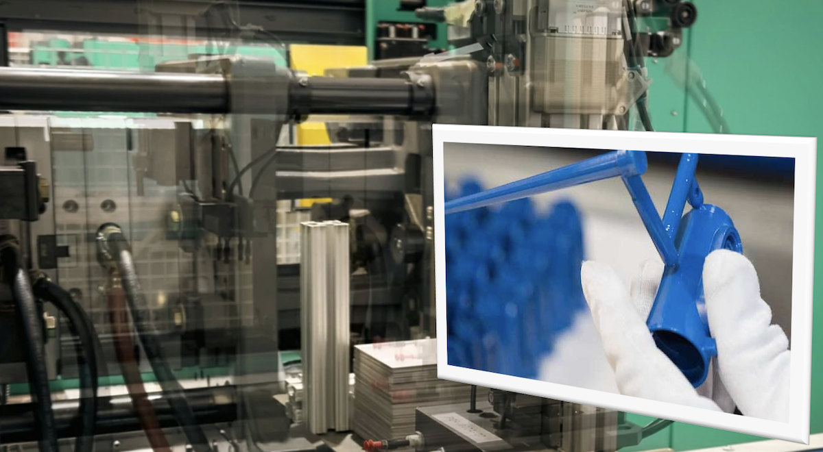
There is no universal answer, but here's a practical framework:
|
Volume Range |
Recommended Process |
Rationale |
|
1–50 units |
3D Printing (FDM, SLS, MJF) |
No tooling cost, fast iteration |
|
50–500 units |
Engineering-grade 3D Printing or Rapid Tooling |
Bridge the gap, test market |
|
500–5,000 units |
Rapid Tooling (Aluminum molds) |
Lower tooling cost, faster turnaround |
|
5,000–50,000 units |
Low-Volume Injection Molding (Steel molds) |
Best per-part economics |
|
50,000+ units |
Production Injection Molding |
Maximum efficiency, lowest cost |
Important note: If your part requires tight tolerances (±0.05 mm), Class A surface finish, or must pass regulatory certification, you may need to switch to injection molding earlier in the volume range
The Smartest Strategy: Use 3D Printing and Injection Molding Together
This is the most important section for product development teams. Instead of viewing 3D printing and injection molding as competitors, the smartest approach is to use them as sequential stages in a unified product development workflow.
This is exactly how leading product development companies operate—and it's the core philosophy behind TEAM Rapid's integrated manufacturing services.
Stage 1: Concept Development — Use 3D Printing
Goal: Validate form, fit, and basic function quickly.
Test objectives:
- Appearance and aesthetics
- Size and proportions
- Ergonomics and user interaction
- Basic assembly verification
Recommended processes: FDM, SLA, or SLS depending on requirements.
Typical timeline: 1–5 days per iteration.
At this stage, speed matters more than material performance. You want to fail fast, learn quickly, and iterate cheaply.
Stage 2: Functional Testing — Use Engineering-Grade 3D Printing
Goal: Validate mechanical performance, assembly, and design robustness.
Test objectives:
- Assembly with mating components
- Basic mechanical performance (snap fits, living hinges, load-bearing features)
- Design changes based on test results
- Environmental testing (if applicable)
Recommended processes: SLS with Nylon 12, MJF, or FDM with engineering materials (PC, carbon-fiber nylon, ASA).
Typical timeline: 3–7 days per iteration.
This stage bridges the gap between "it looks right" and "it works right." Engineering-grade 3D printing allows you to test real-world performance before committing to tooling.
Stage 3: Design for Manufacturing (DFM)
Goal: Optimize the design for injection molding before cutting steel.
Key activities:
- DFM analysis (wall thickness, rib design, boss placement)
- Material selection based on final application requirements
- Wall thickness optimization (uniform wall thickness to prevent sink marks and warpage)
- Draft angle analysis (typically 1–3° per side)
- Gate location planning
- Ejection strategy
Why this stage matters: Skipping DFM is the #1 reason injection molding projects fail or require expensive mold modifications. A proper DFM review can save thousands of dollars and weeks of timeline.
Stage 4: Bridge Production — Rapid Tooling and Low-Volume Injection Molding
Goal: Produce market-ready parts at low-to-medium volumes while finalizing production tooling.
Options:
- Rapid tooling (aluminum molds): Lead time 2–5 weeks, suitable for 500–10,000 parts
- Low-volume injection molding (P20 steel molds): Lead time 3–6 weeks, suitable for 10,000–100,000 parts
- Production tooling (H13 hardened steel): Lead time 6–12 weeks, suitable for 100,000+ parts
This staged approach ensures that:
- You never over-invest in tooling before the design is validated
- You can get functional parts to market quickly
- Your final production tooling is based on a proven, optimized design
- Total development cost is minimized while quality is maximized
Decision Checklist: How to Choose the Right Process
Use this checklist to make a data-driven decision for your specific project:
What is your target production quantity?
- Below 200 units → 3D Printing
- 200–5,000 units → Rapid Tooling / Low-Volume Injection Molding
- Above 5,000 units → Production Plastic Injection Molding
What are your mechanical requirements?
- Low stress, non-structural → 3D Printing may suffice
- High cyclic loading, impact, or fatigue → Injection Molding
What tolerances do you need?
- ±0.2 mm or looser → 3D Printing acceptable
- ±0.1mm or tighter → Injection Molding required
What surface finish is required?
- Functional (no cosmetic requirement) → 3D Printing acceptable
- Class A / cosmetic → Injection Molding
What is your timeline?
- Need parts in days → 3D Printing
- Can wait 3–6 weeks for tooling → Injection Molding
Will the design change?
- High likelihood of changes → Start with 3D Printing
- Design is frozen → Proceed to Injection Molding
Are there regulatory or certification requirements?
- Yes → Injection Molding (more consistent, easier to validate)
- No → Either process may work
Frequently Asked Questions
Q1: Can I use 3D printed parts as end-use parts in my product?
Yes, for low-volume applications (under 200 units), non-critical structural roles, or highly customized parts. However, for high-volume production, safety-critical applications, or parts requiring tight tolerances, injection molding is strongly recommended.
Q2: How much does rapid tooling cost compared to production tooling?
Rapid tooling (aluminum molds) typically costs 2,000– 8,000, while production steel molds range from 10,000– 50,000+ depending on part size, complexity, number of cavities, and surface finish requirements.
Q3: What is the typical lead time for rapid tooling?
Aluminum rapid tooling can be delivered in 2–4 weeks, compared to 6–12 weeks for hardened steel production molds.
Q4: Can I switch from 3D printing to injection molding mid-project?
Absolutely. This is the recommended workflow. Start with 3D printing for design validation, then transition to rapid tooling and injection molding once the design is finalized. The key is to perform proper DFM analysis before cutting the mold.
Q5: What materials are available for low-volume injection molding?
Virtually all injection-moldable thermoplastics are available, including ABS, PC, Nylon (PA6, PA66, PA12), PP, POM, TPE/TPU, PEEK, and glass/carbon-filled variants. Material selection should be based on your application's mechanical, thermal, and chemical requirements.
Q6: How do I know if my part design is ready for injection molding?
A professional DFM review should check for: uniform wall thickness, adequate draft angles, proper rib-to-wall ratios, appropriate gate locations, no undercuts (or planned side-actions), and proper boss design. TEAM Rapid offers free DFM analysis for all tooling inquiries.
From Functional Prototype to Production: Your Next Step
The journey from concept to mass production doesn't have to be a series of disconnected decisions. The most successful product development teams use an integrated approach that leverages the strengths of each manufacturing process at the right stage.
TEAM Rapid can help you move seamlessly through every stage:
3D Printing → Functional Prototypes → Rapid Tooling → Low-Volume Injection Molding → Mass Production
Whether you need a single functional prototype for testing, a bridge production run of 500 parts, or full-scale production tooling for 100,000+ units, our team provides end-to-end support with:
- Free DFM analysis with every tooling inquiry
- Fast turnaround (rapid tooling in as little as 2 weeks)
- Wide material selection (50+ engineering-grade resins)
- Competitive pricing for low-volume and high-volume production
- Quality inspection reports with every shipment
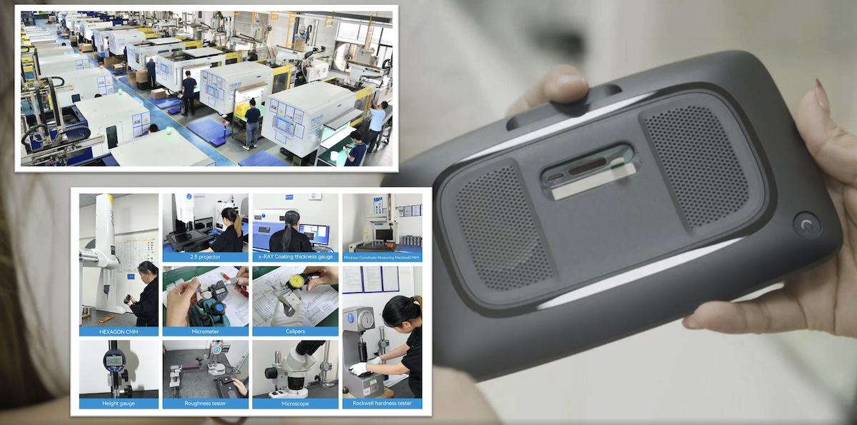
Ready to Get Started?
Submit your project details today and receive a free quote + DFM feedback within 24 hours:
- 3D CAD files (STEP, IGES, SLDPRT, STL, or other formats)
- Material requirements (or let us recommend based on your application)
- Production quantity (prototype, bridge, or mass production)
- Application requirements (mechanical loads, environment, certifications, surface finish)
Let TEAM Rapid help you make the smartest manufacturing decision for your project—from first prototype to final production part, contact us today!



 Contact