
Draft Angle in Injection Molding: Why It Matters and How to Design It Correctly
When designing plastic parts, engineers often obsess over wall thickness, tolerances, and material selection. Yet, one of the most critical design parameters is frequently treated as an afterthought: the draft angle. Draft angle matters because it prevents parts from sticking and protects the mold from wear during ejection, and it is designed correctly by applying a specific taper-usually 0.5° to 2° or more-to all vertical walls based on the plastic material, wall depth, and surface texture.
At TEAM Rapid, we’ve seen brilliant part designs fail on the production floor simply because the draft angle was ignored or miscalculated. A fraction of a degree can determine whether a mold yields thousands of flawless parts or becomes a costly, maintenance-heavy liability.
In this comprehensive guide, we will explore the engineering, economics, and physics of the draft angle in injection molding. More importantly, we will introduce a new viewpoint: Draft angle isn’t merely a geometric requirement to eject a part-it is a strategic lever that directly influences production efficiency, tooling longevity, part quality, and overall manufacturing cost. Here is everything you need to know to master injection molding design guidelines and optimize your next project.
What Is a Draft Angle in Injection Molding
Definition
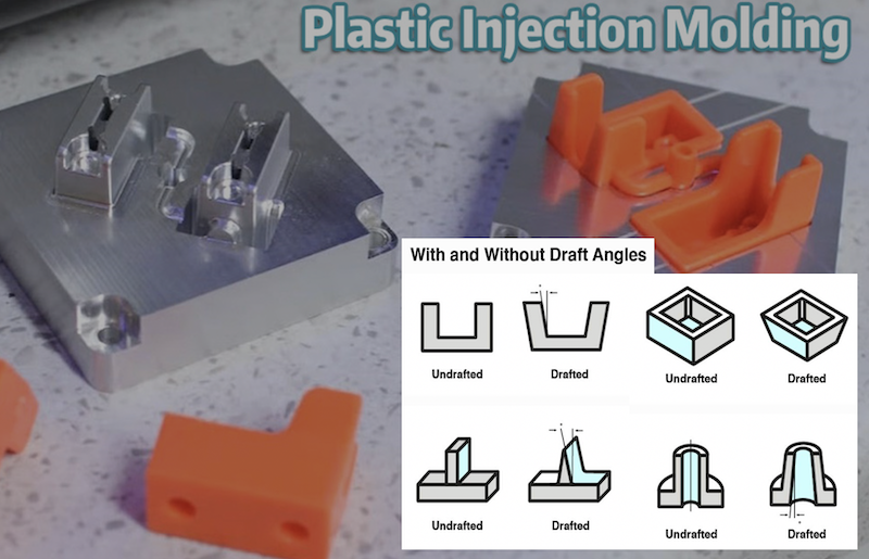
A draft angle (or mold draft) is the taper applied to the vertical walls of a molded part relative to the primary pull direction (the direction the mold opens). Instead of designing a perfectly perpendicular 90-degree wall, a slight angle-usually measured in degrees-is introduced.
Where Draft Angles Are Applied
Draft angles are applied to any surface that is parallel to the direction of mold opening. This includes external walls, internal cores, ribs, bosses, and even engraved text.
Why Every Molded Part Needs Draft
As molten plastic cools, it shrinks. If a wall is perfectly vertical (zero draft), the shrinking plastic grips the mold core with immense force. A draft angle for injection molding breaks this vacuum and friction, allowing the part to release cleanly.
Visualizing Draft Direction: Imagine looking at a part from the top down. The walls should slightly flare outward (for external walls) or inward (for internal cores) as they move in the direction of ejection.
Why Draft Angle Matters More Than You Think
Most basic tutorials will tell you that draft angles simply "help eject parts." While true, this severely understates their impact. Here is the broader engineering and economic impact of a properly designed injection molding draft angle.
1. Easier Part Ejection
- Reduce Ejection Force: A proper draft drastically lowers the tonnage required from the ejector pins, preventing the pins from punching through the plastic.
- Prevent Sticking: It eliminates the vacuum effect that occurs when perfectly flat, vertical walls separate from the mold steel.
2. Better Surface Quality
- Prevent Drag Marks: Without draft, the plastic scrapes against the mold steel during ejection, leaving unsightly vertical lines.
- Protect Textured Finishes: Textures act like microscopic undercuts. Draft allows the part to clear the texture peaks without shearing them off.
3. Longer Mold Life
- Less Wear on Cavity Walls: High ejection forces cause premature wear on the mold steel, especially with abrasive glass-filled resins.
- Reduced Maintenance: Less wear means fewer mold polishings, less downtime, and a longer ROI for your tooling.
4. Faster Production Cycles
- Shorter Ejection Time: Parts that eject smoothly don't require manual intervention or robotic hesitation.
- More Stable Automation: Smooth ejection is mandatory for lights-out manufacturing and reliable drop-and-fall automation.
5. Lower Manufacturing Costs
- Fewer Rejected Parts: Eliminates cosmetic defects and dimensional warping caused by ejection stress.
- Reduced Downtime: Prevents parts from sticking and halting the injection molding machine.
Our point: Stop looking at draft angle as a compromise to your part's geometry. View it as a Design for Manufacturability (DFM) multiplier. Every 0.5° of draft you add in CAD costs $0, but saves thousands of dollars in cycle time, scrap rates, and mold maintenance over the life of the tool.
How Draft Angle Works During the Injection Molding Process
To truly understand injection mold design, you must understand the physics of the molding cycle. Here is how draft interacts with each stage:
- Injection: Molten plastic is forced into the cavity at high pressure, perfectly conforming to the mold walls.
- Packing: Additional plastic is packed in to compensate for initial volumetric shrinkage.
- Cooling: The part begins to solidify.
- Plastic Shrinkage: As the polymer chains relax and cool, the plastic shrinks. On external walls, it shrinks away from the cavity. On internal cores, it shrinks tightly onto the core.
- Part Gripping the Core: The shrinking plastic exerts immense normal force against the core. Without draft, this translates to massive frictional resistance.
- Ejection: The mold opens, and ejector pins push the part.
- Role of Draft Angle: The draft angle converts the normal gripping force into a sliding release. It physically creates a gap between the part and the mold the millisecond ejection begins, breaking the vacuum and eliminating steel-on-plastic scraping.
What Happens If There Is No Draft Angle
Designing with zero draft is a recipe for manufacturing disaster. Instead of just saying "parts stick," let's look at the specific defects that occur:
- Drag Marks & Scratches: Vertical gouges on the part surface.
- Stress Whitening: White stress marks near ejector pins due to excessive pushing force.
- Broken Ribs & Bosses: Internal features snap off and remain stuck in the mold.
- Warped Parts: Uneven ejection forces bend the part while it is still warm.
- Ejector Pin Push-Through: The pins punch completely through the plastic wall.
- Mold Damage: Ejector pins bend, or the mold steel scores and galls.
Comparison: With Draft vs. Without Draft
|
Feature |
With Proper Draft |
Without Draft (Zero Draft) |
|
Ejection |
Smooth, automated release |
Part sticks, requires manual pull |
|
Mold Life |
Long lifespan, minimal wear |
Rapid wear, scoring on cavity walls |
|
Appearance |
Clean, pristine surface |
Severe surface scratches and drag marks |
|
Cycle Time |
Optimized, fast cycles |
Longer cycles, machine alarms |
|
Scrap Rate |
Extremely low |
High, frequent rejected batches |
Recommended Draft Angle Guidelines
As a baseline for your injection molding design guidelines, use the following practical engineering table.
|
Feature |
Recommended Draft |
|
Smooth external walls |
0.5° - 1° |
|
Textured surfaces |
2° - 5° (depending on depth) |
|
Deep ribs |
1° - 2° |
|
Bosses |
0.5° - 1° |
|
Shut-offs |
3° - 5° (Higher draft required to prevent steel-on-steel wear) |
|
Deep cavities |
Increase draft proportionally (add 0.5° for every inch of depth) |
Why deeper features need more draft: As wall depth increases, the cumulative surface area and friction increase. A 1° draft on a 10mm wall provides a small release gap; on a 100mm wall, that same 1° provides a much larger physical gap at the top, ensuring the bottom clears before the top binds.
How Surface Finish Affects Draft Angle Requirements
This is an area where many novice designers fail. Surface texture is essentially a series of microscopic undercuts. If you apply a texture to a zero-draft wall, the plastic will lock into the texture valleys.
Texture Types and Draft Needs
- Polished Molds (SPI Finishes): Require minimal draft (0.5°) because the steel is perfectly smooth.
- VDI / EDM Textures: Created via electrical discharge machining, these have a matte, stippled finish requiring 1° to 2°.
- Mold-Tech / Chemical Etch Textures: These are the most common. The rule of thumb is 1° of draft for every 0.001" (0.025mm) of texture depth.
- Leather Grain & Sandblasting: Deep, aggressive textures that require 3° to 5° of draft to prevent the texture from being sheared off during ejection.
|
Surface Finish |
Typical Draft Required |
|
Mirror Polish (SPI A1) |
0.5° |
|
Fine Texture (Mold-Tech MT11010) |
1° - 1.5° |
|
Medium Texture (Mold-Tech MT11020) |
2° - 3° |
|
Heavy Leather Grain |
3° - 5° |
Draft Angle Recommendations for Different Plastic Materials
Material properties-specifically shrinkage rates, stiffness, and coefficient of friction-dictate draft requirements.
- High Shrinkage Materials (e.g., PP, PE, POM): These shrink tightly onto cores, but they also have a naturally "slippery" low coefficient of friction. They generally require standard draft (0.5°).
- Rigid Materials (e.g., PC, ABS, Nylon): These don't flex easily during ejection and can crack or stress-whiten. They require a full 1° or more.
- Elastomers (e.g., TPU, TPE): These have high friction and tend to "grab" the mold steel. They require significantly larger draft angles (2°+).
- Filled Plastics (Glass/Carbon Fiber): The fibers act like sandpaper on the mold. You must increase the draft by 0.5° to 1° to compensate for the increased friction and mold wear.
|
Material |
Suggested Minimum Draft |
|
ABS |
1° |
|
PC (Polycarbonate) |
1° - 1.5° |
|
PP (Polypropylene) |
0.5° |
|
PE (Polyethylene) |
0.5° |
|
Nylon (PA) |
1° |
|
POM (Acetal) |
0.5° |
|
TPU / TPE |
2° or larger |
|
Glass-Filled Plastics |
Add 0.5° - 1° to base resin draft |
Draft Angle Design for Common Injection Molded Features
To achieve comprehensive injection mold design, you must apply draft to all features, not just the outer shell.
- External & Internal Walls: The baseline. Always draft in the direction of mold opening.
- Ribs: Ribs are notoriously difficult to eject. Use 0.5° to 1° draft. Ensure the base of the rib is not thicker than 60% of the nominal wall to prevent sink marks.
- Bosses: Apply 0.5° to 1° draft to the outside of the boss, and 0.25° to 0.5° to the inside (the core pin).
- Snap Fits: The cantilever arm needs draft to ensure uniform thickness and smooth ejection without stressing the hinge point.
- Living Hinges: The hinge area itself should be drafted to ensure the plastic flows correctly and ejects without tearing.
- Deep Pockets: Require increased draft (up to 2° or 3°) and often require venting to prevent vacuum locks.
- Logos & Text Engraving: Often forgotten! Engraved text acts as a severe undercut if not drafted. Apply at least 2° to 3° draft to raised or recessed lettering.
How Draft Angle Influences Mold Cost
This is a topic for the buyers and project managers. How does a geometric angle affect your bottom line?
- Machining Complexity: CNC milling a tapered wall (draft) is actually easier and faster than milling a perfectly vertical wall, which requires precise Z-axis control and smaller step-overs to avoid tool deflection.
- EDM Requirements: Deep, zero-draft pockets often cannot be milled and require Electrical Discharge Machining (EDM). EDM requires manufacturing copper electrodes, which drastically increases tooling costs and lead times. Draft allows for standard CNC milling.
- Polishing Time: Drafted walls are much easier for mold polishers to access with sandpaper and diamond paste. Zero-draft deep pockets require specialized, time-consuming polishing techniques.
- Tool Life & Maintenance: As mentioned, zero draft causes galling and wear. The cost of welding, re-machining, and re-texturing a damaged mold cavity far outweighs the "cost" of adding draft in the CAD phase.
Pro Tip: Increasing draft during the 3D CAD design phase costs virtually nothing. Modifying a hardened steel mold to add draft after it has been machined can cost thousands of dollars and delay your project by weeks.
Common Draft Angle Design Mistakes
Avoid these frequent pitfalls that we see in DFM reviews at TEAM Rapid:
- Using Zero Draft: "I want perfectly square edges for aesthetics." Solution: Use a 0.5° draft; it is visually imperceptible but mechanically vital.
- Applying Draft in the Wrong Direction: Drafting a core in the same direction as the cavity creates an undercut. Solution: Always draft cores and cavities in the direction of their respective pull.
- Ignoring Textured Surfaces: Applying 0.5° draft to a heavy leather grain texture. Solution: Consult the texture provider's draft chart.
- Forgetting Internal Features: Drafting the outside but leaving internal ribs and bosses at zero. Solution: Run a global draft analysis in your CAD software.
- Overly Tall Ribs Without Draft: Causes the rib to snap off during ejection. Solution: Limit rib height to 3x the nominal wall thickness and apply 1° draft.
- Mixing Inconsistent Draft Angles: Using 1° on one half of a mating enclosure and 2° on the other, resulting in mismatched parting lines. Solution: Standardize draft angles across assembly components.
How Engineers Can Verify Draft Angle Before Manufacturing
Never send a 3D model to a rapid tooling shop without verifying the draft. Implement these DFM practices:
- CAD Draft Analysis: Tools like SolidWorks, Creo, and NX have built-in "Draft Analysis" features. They use a color map (usually red for negative/zero draft, green for positive) to visually highlight problem areas.
- Mold Flow Analysis: Software like Autodesk Moldflow can simulate ejection forces and predict where parts will stick or warp based on draft angles.
- DFM Review: Always request a DFM report from your molding partner.
- Early Supplier Feedback: Engage with your tooling engineer before finalizing the CAD. At TEAM Rapid, we review draft angles during the initial quoting phase to save our clients time and money.
Real Project Example: Solving Ejection Problems by Adjusting Draft Angle
The Challenge: A client designing a consumer electronics enclosure (made of PC/ABS) initially submitted a CAD model with a 0.2° draft on the exterior walls to maintain a "sharp, boxy" aesthetic. The walls were 45mm deep and featured a fine Mold-Tech texture.
The Result: During T1 (first article) sampling, the parts stuck to the cavity. When forced out, they exhibited severe drag marks, the texture was sheared off near the parting line, and the cycle time had to be extended by 8 seconds to allow for extra cooling and manual intervention.
The Solution: Our engineering team at TEAM Rapid recommended increasing the draft to 1.5°. The client was initially hesitant about the aesthetic change. We produced a 3D-printed visual prototype to prove that the 1.5° taper was visually imperceptible to the human eye.
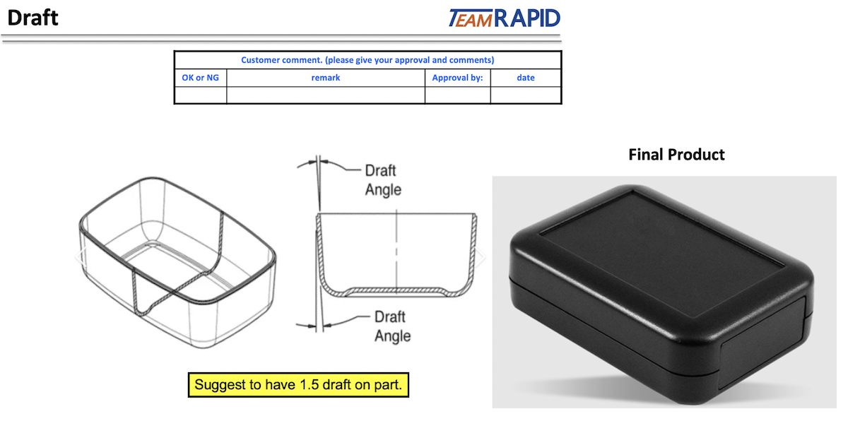
The Outcome: After modifying the mold, ejection was flawless. The texture remained pristine, stress whitening was eliminated, and the cycle time was reduced by 12 seconds. Over a production run of 100,000 parts, this saved the client over 300 hours of machine time and completely eliminated cosmetic scrap.
Draft Angle Design Checklist
Use this actionable checklist before releasing your 3D CAD files for tooling:
- Add draft early in the initial CAD design phase, not as a final tweak.
- Consider parting line direction and ensure draft aligns with the pull direction.
- Increase draft for deeper walls (add 0.5° for every additional inch of depth).
- Add extra draft for textured surfaces (1° per 0.001" of texture depth).
- Verify internal features (ribs, bosses, pockets) separately from external walls.
- Check material shrinkage and adjust draft for high-shrinkage or filled resins.
- Perform CAD draft analysis using color-mapping tools to catch zero-draft zones.
- Review with mold engineers and request a comprehensive DFM report.
- Validate with prototyping before committing to hard tooling release.
Frequently Asked Questions (FAQ)
Is a draft angle always necessary in injection molding?
Almost always. The only exceptions are very shallow parts (under 2mm deep) made from highly flexible materials, or parts utilizing expensive, complex side-actions and lifters for specific vertical walls. For 99% of designs, draft is mandatory.
What is the minimum draft angle for plastic parts?
The absolute minimum is typically 0.25° to 0.5° for smooth, shallow walls in low-friction materials like PP or POM. However, 1° is the recommended industry standard for safe, reliable production.
Can textured parts use a 1° draft?
Only if the texture is extremely fine (like a light matte finish). For standard Mold-Tech textures, you need at least 1.5° to 2°. For heavy leather grains, you need 3° to 5°.
How does wall height affect draft angle?
The taller the wall, the more friction and shrinkage force is generated. As a rule of thumb, add 0.5° of draft for every additional inch (25.4mm) of wall depth beyond the first inch.
Which materials require larger draft angles?
Rigid, brittle materials like Polycarbonate (PC) and acrylic, high-friction elastomers like TPU, and highly abrasive glass-filled or carbon-filled plastics require larger draft angles.
Can too much draft affect assembly or appearance?
Excessive draft (e.g., 5° on a standard wall) can create a noticeable taper that affects the aesthetic design and cause misalignment when mating two halves of an enclosure. Stick to the 0.5° to 2° range unless texture or depth dictates otherwise.
How do CAD tools analyze draft angles?
CAD software uses a "Draft Analysis" tool that calculates the angle of every face relative to a user-defined pull direction. It applies a color gradient to visually highlight undercuts (red), zero draft (yellow), and positive draft (green).
How can I reduce mold costs by optimizing draft?
By adding proper draft, you allow the mold maker to use standard 3-axis CNC milling instead of 5-axis machining or EDM. You also reduce mold polishing time and extend the life of the tool, lowering the injection molding cost per part over the production run.
Conclusion
The draft angle in injection molding is far more than a simple geometric tweak; it is a fundamental pillar of successful manufacturing. Proper draft improves manufacturability, elevates product quality, ensures tooling durability, and maximizes production efficiency.
Designing your draft correctly from the very beginning of the CAD process helps you avoid costly tooling modifications, production delays, and high scrap rates. It is the ultimate example of "measure twice, cut once" in plastic manufacturing.
Don't leave your tooling success to chance. Collaborate with experienced mold engineers during the design phase to optimize part performance and manufacturing outcomes.
Ready to optimize your part design? The engineering experts at TEAM Rapid are ready to review your 3D models, provide comprehensive DFM analysis, and deliver high-quality rapid tooling and plastic injection molding services. Contact us today to get your project started!


 Contact