
Injection Molding Cooling System Design: How to Reduce Cycle Time, Improve Part Quality, and Lower Production Cost
Injection molding cooling system design is the engineering process of strategically placing and configuring cooling channels, baffles, and thermal management features within a mold to remove heat uniformly and efficiently, thereby minimizing cycle time, preventing part defects such as warpage and sink marks, and optimizing overall production cost.
If you ask most engineers what determines injection molding productivity, they'll mention injection speed, clamp force, or material flow. But the truth is far simpler—and often overlooked: Cooling accounts for 70–80% of the total injection molding cycle time. That means the single biggest lever you have to reduce cycle time, increase output, and lower per-part cost is not the injection unit. It's the cooling system inside your mold.
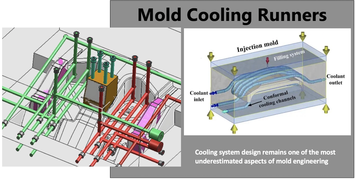
Yet cooling system design remains one of the most underestimated aspects of mold engineering. Many molds are built with cooling channels placed "where there's room" rather than where heat actually needs to be removed. The result? Longer cycles, warped parts, sink marks, uneven shrinkage, residual stress, and dimensional instability—all of which drive up scrap rates and production costs.
This article provides a comprehensive engineering guide to injection molding cooling system design, covering:
· How cooling affects cycle time and part quality
· Heat transfer mechanisms and cooling time calculation
· Cooling channel design parameters (diameter, spacing, distance, flow rate)
· Traditional vs. conformal cooling
· Material-specific and geometry-specific cooling strategies
· CAE simulation for cooling optimization
· Common design mistakes and how to fix existing molds
· The business case: how saving 2–5 seconds per cycle translates into significant annual ROI
Whether you're designing a new mold or troubleshooting an existing one, this guide will help you make informed decisions that balance thermal efficiency, part quality, tooling cost, and production output.
Understanding the Injection Molding Cycle
The Four Main Stages of an Injection Molding Cycle
Every plastic injection molding cycle consists of four primary stages:
- Mold Closing – The two halves of the mold close and clamp.
- Injection and Filling – Molten plastic is injected into the cavity.
- Packing/Holding – Additional pressure is applied to compensate for shrinkage.
- Cooling – The part solidifies inside the mold.
- Mold Opening and Ejection – The mold opens and the part is ejected.
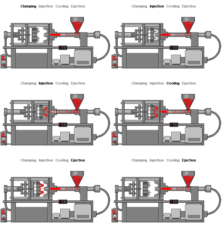
While injection and packing are critical for filling and dimensional accuracy, the cooling phase is where the part transitions from a molten state to a solid, dimensionally stable component. This phase cannot be rushed without consequences—but it can be optimized.
Where Does Cooling Time Fit Into Total Cycle Time?
A simplified cycle-time equation:
Total Cycle Time = Injection Time + Packing Time + Cooling Time + Mold Opening/Ejection Time
In a typical cycle:
|
Phase |
Typical Duration |
% of Total Cycle |
|
Injection + Packing |
2–5 seconds |
10–20% |
|
Cooling |
15–40 seconds |
60–80% |
|
Mold Open/Close + Ejection |
3–6 seconds |
10–20% |
This is why injection molding cooling time is the primary target for cycle time reduction. Even a 10% improvement in cooling efficiency can yield a 7–8% reduction in total cycle time—translating directly into more parts per hour and lower unit cost.
Key Insight: A mold's cooling system is not just a temperature-control system. It is a production-rate system and a part-quality system.
Heat Transfer Fundamentals in Injection Molding
Understanding how heat moves from the part to the coolant is essential for effective cooling design.
Conduction: Heat Flow Through the Part and Mold Steel
Heat must first conduct from the center of the plastic part to its surface, then through the mold steel to the cooling channel wall. The rate of conduction depends on:
· Thermal conductivity of the plastic (typically 0.1–0.4 W/m·K for most polymers)
· Thermal conductivity of the mold steel (typically 25–40 W/m·K for P20 or H13)
· Part wall thickness – This is the dominant factor
Convection: Heat Transfer at the Channel Wall
Once heat reaches the cooling channel surface, it is carried away by the flowing coolant (usually water or water-glycol mixture). Convective heat transfer depends on:
· Coolant flow velocity
· Coolant temperature
· Channel surface condition
· Flow regime (laminar vs. turbulent)
The Non-Linear Relationship Between Wall Thickness and Cooling Time
This is a critical point that many engineers underestimate:
Cooling time is proportional to the SQUARE of wall thickness.
The simplified cooling time formula:
tc=π2⋅αs2⋅ln(π28⋅Te−TwTm−Tw)
Where:
· tc = cooling time
· s = wall thickness
· α = thermal diffusivity of the polymer
· Tm = melt temperature
· Tw = mold wall temperature
· Te = ejection temperature
Practical implication: Doubling the wall thickness quadruples the cooling time. This is why thick sections are the primary source of long cycles and why conformal cooling becomes especially valuable for thick-walled parts.
Cooling Channel Design: Key Parameters
Channel Diameter
Standard cooling channel diameters range from 6 mm to 12 mm (0.25" to 0.5").
· Larger diameter → higher flow capacity, but more difficult to drill in tight areas
· Smaller diameter → easier to route, but higher pressure drop and lower heat removal capacity
· Recommended starting point: 8–10 mm for most molds
Channel Spacing (Pitch)
The distance between adjacent cooling channels directly affects temperature uniformity across the mold surface.
· Typical spacing: 3–5× the channel diameter
· Too wide → temperature variation across the cavity surface → uneven cooling → warpage
· Too narrow → weakens the mold structure, increases machining cost
Rule of thumb: Channel center-to-center distance should be approximately 30–50 mm for most applications.
Distance from Cavity Surface
The distance between the cooling channel centerline and the cavity surface is one of the most critical parameters.
· Closer to cavity → faster heat extraction, more uniform surface temperature
· Too close → risk of thermal fatigue, cracking, or interference with ejector pins and other features
· Recommended distance: 1–2× the channel diameter from the cavity surface (typically 10–20 mm)
Coolant Flow Rate and Turbulence
To achieve effective convective heat transfer, the flow inside the channel should be turbulent (Reynolds number > 4,000, ideally > 10,000).
· Laminar flow → poor heat transfer, boundary layer insulates the channel wall
· Turbulent flow → disrupts the boundary layer, dramatically improves heat transfer coefficient
How to ensure turbulent flow:
· Use smaller diameter channels at higher pressure
· Increase pump capacity
· Use baffles, bubblers, or turbulators in large channels
Coolant Temperature
· Amorphous materials (ABS, PC, PMMA): mold temperature 60–90°C
· Semi-crystalline materials (PP, PA, POM): mold temperature 40–80°C
· Lower mold temperature → faster cooling but higher risk of residual stress, poor surface finish, and warpage
Simply lowering the coolant temperature is not always the answer. The goal is uniform temperature, not just low temperature.
Traditional Cooling vs. Conformal Cooling
Traditional (Straight-Drilled) Cooling Channels
Most injection molds use straight-drilled cooling channels. These are:
· Easy and inexpensive to manufacture
· Limited to linear paths
· Often unable to follow complex part geometry
Limitation: In areas with complex geometry (ribs, bosses, deep cores), straight channels cannot get close enough to the cavity surface. This creates hot spots that extend cooling time and cause defects.
Conformal Cooling Channels
Conformal cooling uses channels that follow the contour of the part geometry, maintaining a consistent distance from the cavity surface.
Advantages:
· 20–50% reduction in cooling time for complex parts
· More uniform temperature distribution
· Reduced warpage and residual stress
· Better surface quality
Manufacturing methods:
· Metal 3D printing (DMLS/SLM)
· Vacuum brazing of layered inserts
· Diffusion bonding
When to use conformal cooling:
· Thick-walled sections
· Complex geometry with deep cores or ribs
· High-volume production where cycle time savings justify the higher tooling cost
· Parts with tight dimensional tolerances
Cost consideration: Conformal cooling inserts typically cost 2–5× more than traditional cooling. However, for production volumes above 100,000–500,000 parts, the cycle time savings often deliver a positive ROI within months.
Cooling Design for Different Mold Geometries
Flat Parts
· Straight channels on both core and cavity sides
· Ensure uniform spacing
· Watch for edge effects (corners cool faster than center)
Deep Core Geometry
· Use baffles (flat plates inserted into drilled holes) or bubblers (fountain-type inserts) to bring coolant into deep core areas
· Consider thermal pins (heat pipes) for very deep, narrow cores
· Conformal cooling is highly effective here
Ribbed Sections and Bosses
· Ribs and bosses create localized thick sections that cool slowly
· Place cooling channels directly beneath these features
· If inaccessible, consider thermal pins or high-conductivity inserts (beryllium copper)
Thin-Walled Parts
· Cooling time is already short
· Focus on temperature uniformity rather than speed
· Avoid over-cooling, which can cause ejection problems
Material-Specific Cooling Considerations
Amorphous Polymers (ABS, PC, PMMA, PS)
· No sharp crystallization point; solidify gradually
· Less sensitive to cooling rate
· Lower mold temperatures acceptable (but watch for residual stress in PC)
· Cooling time primarily determined by wall thickness and ejection temperature
Semi-Crystalline Polymers (PP, PE, PA, POM, PBT)
· Sharp crystallization temperature; release significant latent heat during crystallization
· Require more cooling energy per unit volume
· Mold temperature significantly affects crystallinity, shrinkage, and mechanical properties
· Higher mold temperatures may be needed for dimensional stability (e.g., PA6 at 80°C)
Glass-Fiber Reinforced Materials
· Higher thermal conductivity than unfilled resins (cool slightly faster)
· But fiber orientation creates anisotropic shrinkage
· Temperature uniformity becomes even more critical to prevent differential shrinkage and warpage
High-Temperature Engineering Plastics (PEEK, PEI, PPS)
· Require very high mold temperatures (120–180°C)
· Often use oil-based temperature control units instead of water
· Cooling channels must be designed for higher operating temperatures and thermal expansion
Using CAE Simulation for Cooling Optimization
Why Simulate Before Cutting Steel?
Cooling channel layout is extremely difficult to modify after the mold is built. A single misplaced channel can add seconds to every cycle for the life of the mold.
CAE tools like Autodesk Moldflow, Moldex3D, or Sigmasoft allow you to:
· Predict temperature distribution across the part
· Identify hot spots before they become production problems
· Optimize channel layout, diameter, and flow rate
· Compare traditional vs. conformal cooling performance
· Estimate cooling time and its contribution to total cycle time
What to Look for in a Cooling Simulation
· Maximum temperature variation across the part surface (target: < 5–10°C)
· Cooling time to reach ejection temperature
· Heat flux distribution – identify areas where heat removal is insufficient
· Pressure drop across the cooling circuit – ensure adequate flow reaches all channels
TEAM Rapid's Approach
At TEAM Rapid, we integrate Moldflow analysis into our injection mold design process from the earliest stages. This allows us to validate cooling performance before any steel is cut, reducing the risk of costly mold modifications and ensuring optimal cycle time from the first shot.
Common Cooling System Design Mistakes
|
Mistake |
Consequence |
Solution |
|
Channels too far from cavity surface |
Slow, uneven cooling; hot spots |
Move channels closer; use baffles or conformal cooling |
|
Uneven channel distribution |
Temperature gradient → warpage |
Balance channel layout; simulate before building |
|
Ignoring pressure drop |
Insufficient flow to far channels |
Use parallel circuits; increase pump capacity |
|
Using laminar flow |
Poor heat transfer |
Increase flow velocity; use turbulators |
|
Same cooling for core and cavity |
Differential shrinkage |
Design separate circuits with independent temperature control |
|
No consideration for ejection side |
Parts stick or deform |
Ensure adequate cooling on core side |
|
Overlooking thermal expansion |
Channel misalignment at operating temperature |
Account for thermal growth in design |
Optimizing Cooling on Existing Molds
Not every optimization requires a new mold. For existing tooling, consider these steps:
Measure and Analyze
· Break down the actual cycle: how much time is cooling vs. injection vs. mold open/close?
· Use surface pyrometers or thermal cameras to identify hot spots
· Measure coolant flow rate and temperature at inlet and outlet of each circuit
Quick Wins
· Increase flow rate – Often the simplest improvement. Check for partially closed valves or clogged channels.
· Lower coolant temperature – Within material-appropriate limits
· Add external cooling – For accessible hot spots, consider supplementary air or water jets (temporary solution)
· Clean cooling channels – Scale and corrosion reduce heat transfer by 20–40%
Medium-Term Improvements
· Add baffles or bubblers to deep cores
· Insert thermal pins (beryllium copper or heat pipe) in hot spots
· Re-plumb cooling circuits to balance flow
Why Cooling Optimization Often Beats Other Approaches
Many manufacturers try to reduce cycle time by increasing injection speed or reducing packing time. While these can help, they often introduce new problems (flash, short shots, sink marks). Cooling optimization is usually the safest and most effective path to cycle time reduction because it addresses the largest time component without changing the filling or packing behavior.
The Business Case: From Seconds to Dollars
Let's put real numbers to the impact of cooling optimization.
Example:
· Current cycle time: 35 seconds
· Cooling time: 25 seconds
· Optimization reduces cooling by 4 seconds → new cycle: 31 seconds
· Improvement: 11.4%
Annual impact (running 24/5):
|
Metric |
Before |
After |
|
Parts per hour |
102.8 |
116.1 |
|
Parts per year |
1,069,000 |
1,207,000 |
|
Additional output |
— |
+138,000 parts/year |
At a part price of 0.50,that′s∗∗ 69,000 in additional annual revenue** from a single 4-second improvement.
Now consider that the cost of a conformal cooling insert might be 3,000– 8,000. The payback period is measured in weeks, not years.
This is why cooling system design is not just an engineering exercise—it's a business decision with measurable ROI.
Cooling System Design Guidelines: Summary Checklist
Use this checklist when designing or reviewing a cooling system:
· Cooling channels placed within 1–2× channel diameter from cavity surface
· Channel spacing: 3–5× diameter for uniform temperature
· Flow regime is turbulent (Re > 10,000)
· Separate circuits for core and cavity
· Pressure drop balanced across all circuits
· Hot spots identified and addressed (baffles, thermal pins, conformal cooling)
· Material-specific mold temperature targets confirmed
· CAE simulation performed before finalizing layout
· Coolant type and temperature appropriate for material
· Accessibility for maintenance and cleaning considered
Conclusion: Designing Cooling Systems for Faster, More Stable Production
Effective injection molding cooling system design is a balance between:
· Heat-transfer efficiency – removing heat fast enough to meet cycle time targets
· Temperature uniformity – ensuring consistent part quality and dimensional stability
· Part quality – minimizing warpage, sink marks, and residual stress
· Tooling cost – selecting the right cooling technology for the production volume
· Cycle time – maximizing output without sacrificing quality
The central principle is this:
"Don't design cooling channels simply to remove heat. Design them to remove heat uniformly, efficiently, and economically."
At TEAM Rapid, we bring this philosophy to every project. Our capabilities include:
· Injection mold design with optimized cooling from day one
· Moldflow analysis to validate cooling performance before cutting steel
· Rapid tooling for prototype and bridge production
· Production tooling with conformal cooling options for high-volume applications
Whether you need a prototype mold with 500 shots or a production tool running millions of cycles, our engineering team designs cooling systems that deliver measurable results—faster cycles, better parts, and lower cost per unit.
Get a free quote or contact our engineering team to discuss your cooling optimization needs.


 Contact