
Rib and Boss Design Guidelines for Strong Plastic Parts: Complete Injection Molding Design Guide
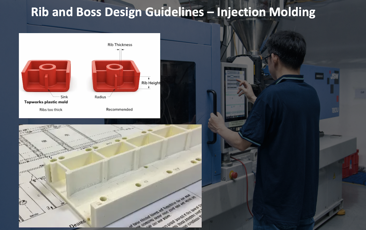
When it comes to plastic part design, many novice engineers make a critical mistake: they try to make a part stronger by simply making the walls thicker. In the world of injection molding, more material does not equal a better part. In fact, it usually leads to catastrophic failures, cosmetic defects, and skyrocketing costs. Actually, the secret to strong, lightweight, and cost-effective plastic parts lies in smart geometry-specifically, rib and boss design. Rib and boss design guidelines for strong plastic parts dictate using thin ribs to maximize structural stiffness and properly gusseted bosses for secure assembly, enabling a uniform wall thickness that prevents sink marks and reduces manufacturing costs.
At TEAM Rapid, we see thousands of 3D CAD files every year. The designs that succeed in production are those that master the interplay of ribs and bosses. In this comprehensive plastic injection molding design guide, you will learn the exact rib design injection molding principles and boss design guidelines needed to optimize your parts for manufacturing.
Why Rib and Boss Design Matters More Than Wall Thickness
The Hidden Cost of Poor Plastic Part Design
Thick walls in injection molding cool slower than thin walls. This differential cooling creates internal stresses, leading to warpage, voids, and severe sink marks on cosmetic surfaces. Furthermore, thicker walls require more raw material and significantly increase cycle times, directly inflating your piece price.
How Proper Design Improves Strength Without Increasing Material Cost
By utilizing ribs to increase the moment of inertia and bosses to provide secure mounting points, you can maintain a uniform, thin nominal wall thickness. This ensures rapid, even cooling, eliminates sink marks, and reduces material usage, all while achieving superior structural integrity.
What You’ll Learn in This Guide
- The physics and economics of ribs vs. thick walls.
- Exact dimensional formulas and golden rules for ribs and bosses.
- How to design for specific fasteners and plastic materials.
- How your CAD design directly impacts mold manufacturing costs and cycle times.
What Are Ribs and Bosses in Injection Molding
What Is a Rib
A rib is a thin, fin-like protrusion extending from a wall or surface.
- Purpose: To increase the stiffness and structural strength of a part without increasing the nominal wall thickness.
- Common Applications: Electronic housings, automotive interior panels, and structural brackets.
- Typical Geometries: Straight, crossed (grid), or radial patterns.
What Is a Boss
A boss is a cylindrical protrusion designed to facilitate assembly.
- Purpose: To provide a localized, reinforced area for fastening (screws, inserts, pins) or for locating/aligning parts.
- Types of Bosses: Screw bosses, insert bosses, through bosses, and blind bosses.
- Typical Applications: Enclosures that need to be screwed together, gear mounts, and hinge points.
How Ribs and Bosses Work Together (A Structural System)
Instead of viewing ribs and bosses as isolated features, expert engineers view them as a unified structural system. A boss acts as a localized load-bearing node, while ribs act as the structural "highways" that distribute the mechanical stress from the boss across the broader nominal wall of the part. If a boss is the anchor, the ribs are the chains holding it in place.
Why Engineers Use Ribs Instead of Thicker Walls
Many competing articles skip the economic benefits of rib design. Let’s look at the hard manufacturing realities. Adding ribs instead of thickening walls provides massive advantages in weight reduction, material savings, improved cooling time, better dimensional stability, and lower manufacturing costs.
Comparison Table: Solid Wall vs. Rib Reinforcement
|
Feature |
Thick Wall |
Proper Rib Design |
|
Weight |
High |
Low |
|
Sink Marks |
High Risk |
Low Risk |
|
Cooling Time |
Longer (Increases cycle cost) |
Shorter (Reduces cycle cost) |
|
Warpage |
More (Due to uneven cooling) |
Less (Uniform cooling) |
|
Material Cost |
Higher |
Lower |
Rule of thumb in injection molding: Cooling time is proportional to the square of the wall thickness. Halving the wall thickness reduces cooling time by 75%.
Understanding the Relationship Between Wall Thickness and Rib Thickness
The Golden Rule
The most critical rule in rib design injection molding is that the rib must be thinner than the nominal wall it attaches to. If a rib is too thick at its base, it creates a localized mass of plastic that cools slower than the surrounding wall, pulling material inward and creating a visible sink mark on the opposite cosmetic surface.
Recommended Rib Thickness Percentage
The base of the rib should generally be 40% to 60% of the nominal wall thickness.
|
Material |
Recommended Rib Thickness (% of Nominal Wall) |
|
ABS |
50-60% |
|
PP (Polypropylene) |
50-70% (PP shrinks more, so slightly thinner is better) |
|
PC (Polycarbonate) |
50-60% |
|
PA (Nylon) |
40-60% |
|
PBT |
50-60% |
Rib Design Guidelines Every Engineer Should Know
To ensure moldability and part strength, follow these practical formulas and guidelines:
- Rib Thickness: 50% of nominal wall (max 60% for unfilled materials, 40% for glossy surfaces).
- Rib Height: Maximum 3x to 5x the nominal wall thickness. Taller ribs are prone to molding difficulties and buckling.
- Draft Angle: 0.5° to 1.5° per side to ensure easy ejection.
- Base Radius: 0.25x to 0.5x the nominal wall thickness to reduce stress concentration.
- Rib Spacing: Minimum distance between ribs should be at least 2x the nominal wall thickness to allow for proper cooling and tool steel strength.
- Maximum Aspect Ratio: Keep the height-to-thickness ratio below 5:1 to prevent the mold core from deflecting during injection.
Design Formula Summary: The Physics of Stiffness
Why make a rib tall instead of thick?
Stiffness is governed by the Moment of Inertia (I) for a rectangular cross-section: I = (b × h?) / 12 (where b = thickness, h = height).
Because height is cubed, doubling the height of a rib increases its stiffness by 8 times, whereas doubling the thickness only increases stiffness by 2 times. Always prioritize rib height over thickness.
Boss Design Guidelines for Strong Screw Connections
Types of Bosses
- Screw Boss: Standard threaded or self-tapping screw reception.
- Insert Boss: Designed to house brass heat-set or ultrasonic inserts.
- Through Boss: Open at the top, allowing a screw to pass completely through.
- Blind Boss: Closed at the top, preventing the screw from protruding.
Recommended Dimensions & Engineering Calculations
- Boss Outer Diameter (OD): Generally 2x the inner hole diameter (ID) or 2.5x the nominal wall thickness.
- Inner Hole Diameter (ID): Sized according to the fastener (e.g., for an M4 self-tapping screw, ID is typically 3.2mm to 3.4mm depending on the plastic).
- Draft Angle: 0.5° on the outside, 0.25° to 0.5° on the inside hole.
- Base Radius: 0.5x nominal wall thickness.
Calculation Example: If your nominal wall is 2.0mm and you are using an M3 self-tapping screw (requires a 2.4mm pilot hole).
- ID = 2.4mm.
- Boss OD = 2.4mm × 2 = 4.8mm.
- Because the Boss OD (4.8mm) is much thicker than the wall (2.0mm), you must core out the base or use supporting ribs to prevent a massive sink mark.
Designing Bosses for Different Fastening Methods
Choosing the right boss design for your fastener is crucial for assembly strength.
|
Fastening Method |
Boss Design Requirement |
Best Material Choice |
|
Self-Tapping Screws |
Deep hole, specific ID for thread cutting, no metal insert. |
PC, ABS, Nylon |
|
Machine Screws |
Requires a threaded metal insert molded in or pressed in. |
Any rigid plastic |
|
Heat-Set Inserts |
Tapered hole with a small lead-in chamfer for the heated brass insert. |
PC, ABS, Acetal (POM) |
|
Ultrasonic Inserts |
Straight or slightly tapered hole with an interference fit and energy directors. |
PC, ABS, Nylon |
|
Thread Forming Screws |
Similar to self-tapping but requires higher hoop strength (thicker boss wall). |
Glass-filled Nylon, PBT |
How to Connect Bosses with Supporting Ribs
This is one of the most valuable DFM (Design for Manufacturability) topics. Isolated bosses fail. When torque is applied to a screw in a standalone boss, the stress concentrates at the base, leading to cracking or boss breakage.
How Support Ribs Distribute Load
Support ribs (often called gussets) act as buttresses. They transfer the torsional and axial loads from the boss down into the main structural walls of the part.
Best Rib Layouts
- Cross/Gusset Layout: Use 3 or 4 ribs radiating outward from the boss at 90° or 120° intervals.
- Wall Connection: Always route the support ribs to connect the boss to the nearest vertical sidewall, not just to the flat floor.
- Avoiding Stress Concentration: Ensure the support ribs do not create a massive intersection at the base of the boss. Core out the center of the boss base if the intersection becomes too thick.
Draft Angle Recommendations for Ribs and Bosses
Draft angles are non-negotiable in injection molding. Without them, parts will drag, scratch, or stick in the mold.
|
Surface Finish / Feature |
Recommended Draft Angle |
|
Smooth / Polished Surfaces |
0.5° minimum |
|
Light Texture (e.g., SPI C-3) |
1.0° to 1.5° |
|
Heavy Texture (e.g., MT11010) |
2.0° to 3.0° (Add 1° per 0.025mm of texture depth) |
|
Deep Ribs (>3x wall thickness) |
1.0° to 1.5° (to prevent ejector pin push-through) |
|
Tall Bosses (Outside) |
0.5° to 1.0° |
|
Boss Inner Holes |
0.25° to 0.5° (to grip the core pin tightly) |
Material Selection Affects Rib and Boss Design
Different polymers behave differently in the mold. Your plastic part design must adapt to the material:
- ABS: Great all-rounder. Standard 50% rib thickness rule applies. Good screw retention.
- PP (Polypropylene): High shrinkage. Use thinner ribs (40-50%) to avoid sink. Poor screw retention; use inserts or snap fits instead of self-tapping screws.
- PC (Polycarbonate): High stiffness but prone to stress cracking. Use generous base radii on ribs and bosses. Excellent for heat-set inserts.
- Nylon (PA): High shrinkage and moisture absorption. Needs robust boss designs.
- Glass-Filled Nylon: Extremely stiff but highly abrasive. Ribs can be thinner due to high material stiffness, but mold wear will be high. Excellent screw retention.
- POM (Acetal): High shrinkage, low friction. Excellent for gears and moving parts, but requires careful draft angles and insert designs for bosses.
- PC/ABS: Combines PC strength with ABS flow. Follow standard ABS rib guidelines.
Common Rib Design Mistakes That Cause Part Failure
In our decades of tooling experience, we frequently fix these CAD errors:
- Rib Too Thick: Causes severe sink marks on the opposite cosmetic surface.
- Rib Too Tall: Causes the mold core to deflect during high-pressure injection, resulting in varying wall thicknesses or short shots.
- Sharp Corners: Creates stress concentrators where cracks initiate under load. Always use a base radius.
- No Draft Angle: Causes the part to stick to the core, leading to ejection damage.
- Uneven Spacing: Creates differential cooling, leading to part warpage.
Common Boss Design Mistakes
-
Boss Too Close to Side Wall: Causes localized thickening and sink marks on the exterior wall. Maintain a distance of at least 2x the wall thickness.
-
Boss Without Ribs: Leads to snapped bosses during assembly or use.
-
Boss Too Tall: Creates deep, hard-to-cool mold cores that drag during ejection.
-
Thin Boss Wall: Results in the boss splitting when a screw or insert is driven in.
-
Improper Insert Design: Using an insert with the wrong knurl pattern for the specific plastic, leading to insert spin-out under torque.
How Rib and Boss Design Affects Mold Manufacturing
This is a unique section that competitors rarely discuss, but it dictates your tooling budget.
Mold Steel Machining Difficulty
Deep, thin ribs are a nightmare for CNC machining. Standard end mills cannot reach deep, narrow slots without breaking or deflecting. If your rib aspect ratio is too high, the mold maker must use EDM (Electrical Discharge Machining). EDM is significantly slower and more expensive than CNC milling. Design tip: Keep ribs shallow and wide enough for standard CNC end mills to reduce tooling costs.
Cooling Channel Design
Ribs and bosses act as heat sinks. Deep boss cores and tall rib cores trap heat. If they aren't cooled properly, cycle times skyrocket. Tooling engineers often have to use Beryllium Copper (BeCu) inserts for deep boss cores because BeCu conducts heat 3x faster than standard P20 or H13 mold steel. Designing shorter bosses saves you the cost of expensive BeCu inserts.
Ejection Challenges
Ribs have very little surface area for ejector pins to push against. If a rib is deep and lacks draft, the ejection force will crush or punch through the plastic (ejector pin push-through). Proper draft and polishing of the rib cores are mandatory.
Rib and Boss Design for Different Production Volumes
Your design should match your production strategy:
- Rapid Prototyping (3D Printing/CNC): Ribs can be thicker, and draft angles are less critical. However, 3D printed parts are anisotropic; ribs oriented along the Z-axis will be weak.
- Rapid Tooling (Aluminum/Soft Steel Molds): Avoid extremely deep, thin ribs. Soft aluminum molds wear out quickly and deep cores are prone to breaking in soft tooling. Keep aspect ratios below 3:1.
- Low-Volume Production: Standard steel molds (P20). Standard DFM rules apply.
- Mass Production (Hardened H13 Steel): High-volume molds require maximum cooling efficiency. Conformal cooling channels might be used in thick bosses. Draft angles and polish must be perfect to ensure high-speed, automated ejection.
At TEAM Rapid, we specialize in bridging the gap between rapid prototyping and mass production, ensuring your design is optimized for your specific volume.
Simulation and DFM Analysis Before Tooling
Never cut steel without running a Mold Flow Analysis. Simulation predicts:
- Sink Marks: Identifies thick intersections at rib/boss bases.
- Weld Lines: Shows where plastic flow fronts meet (often at the end of a rib or around a boss). Weld lines in these areas severely weaken the part.
- Air Traps: Highlights deep ribs that need venting to prevent burn marks or short shots.
- Fiber Orientation: Crucial for glass-filled materials. Fibers align along the flow direction; if a rib is filled transversely, it will be brittle.
Real Manufacturing Case Study: Optimizing a Plastic Housing
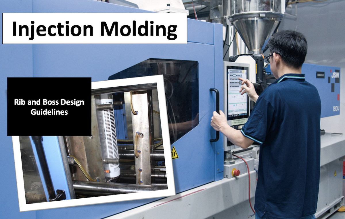
Original Design: A client submitted an ABS electronic housing with 3.0mm thick walls, isolated 8mm tall screw bosses, and 2.5mm thick ribs. Problems: Severe sink marks on the top cover, screw bosses cracking during assembly, and a massive 45-second cooling time.
Optimized Design (By TEAM Rapid Engineers):
- Reduced nominal wall to 2.0mm.
- Reduced rib thickness to 1.0mm (50%) and added gussets to the bosses.
- Cored out the base of the bosses to maintain uniform wall thickness.
Results:
- 18% lighter (Massive material cost savings).
- 25% shorter cooling time (Cycle time dropped from 45s to 34s).
- 40% lower sink marks (Cosmetic surface approved by the client).
- Improved assembly strength (Zero boss cracking during drop tests).
Rib and Boss Design Checklist Before Sending Parts for Tooling
Save this checklist and use it before exporting your STEP files:
- Wall thickness consistency: Are all nominal walls uniform?
- Rib thickness ratio: Are ribs 40-60% of the nominal wall?
- Boss support: Do all bosses have 3 or 4 connecting ribs/gussets?
- Draft angles: Are all vertical faces drafted (min 0.5°, more for texture)?
- Radii: Are sharp internal corners eliminated (min 0.25x wall radius)?
- Spacing: Are ribs spaced at least 2x the wall thickness apart?
- Fastener compatibility: Are boss IDs correct for the specific screw/insert?
- Moldability: Is the rib aspect ratio under 5:1 to avoid EDM and core deflection?
- Ejection: Is there enough surface area for ejector pins on deep ribs?
- Shrinkage compensation: Is the material shrinkage rate applied to the CAD model?
Frequently Asked Questions (FAQs)
How thick should injection molding ribs be?
Typically 40% to 60% of the nominal wall thickness, depending on the material and surface finish requirements.
Why do ribs cause sink marks?
If a rib is too thick at its base, it creates a localized mass of plastic that cools slower than the surrounding wall, pulling the surface inward as it shrinks.
What is the ideal rib height?
Ideally, 3 to 5 times the nominal wall thickness. Taller ribs risk mold core deflection and ejection issues.
Can ribs replace thicker walls?
Yes. Ribs increase the moment of inertia, providing equal or greater stiffness than thick walls while using less material and cooling faster.
What draft angle should ribs have?
A minimum of 0.5° for smooth surfaces, and 1.0° to 2.0°+ for textured surfaces.
How far apart should ribs be?
At least 2 times the nominal wall thickness to ensure proper cooling and maintain mold steel strength.
Should bosses always have support ribs?
Yes, unless they are very short and subjected to minimal torque. Support ribs prevent the boss from snapping under load.
How do you prevent boss cracking?
Use the correct pilot hole size, ensure adequate boss wall thickness (OD = 2x ID), use generous base radii, and add support ribs.
Which plastic materials are best for screw bosses?
Polycarbonate (PC), ABS, and Glass-Filled Nylon offer excellent screw retention and hoop strength.
What is the difference between a rib and a gusset?
A rib is generally a long, thin stiffener. A gusset is a specific type of short, triangular rib used to reinforce a 90-degree intersection, like the base of a boss.
Conclusion
Strong plastic parts come from smart geometry, not just more material. Proper rib and boss design improves strength, reduces weight, eliminates cosmetic defects, and drastically lowers both piece-part and tooling costs. By treating ribs and bosses as a unified structural system and respecting the thermal dynamics of injection molding, you can design parts that are beautiful, durable, and highly profitable to manufacture.
Are you ready to transition your CAD design into high-quality, production-ready tooling? The engineering team at TEAM Rapid is here to help. From DFM analysis and Moldflow simulation to rapid tooling and high-volume mass production, we ensure your plastic part design is optimized for success. Contact us today for a free DFM review of your next project!




 Contact