
Tolerance Standards in Injection Molding: What's Realistic? A Practical Guide for Engineers
When designing plastic components, specifying the right tolerances is the bridge between a functional part and a manufacturing nightmare. Actually we can have the answer here: A realistic injection molding tolerance is typically ±0.1 mm to ±0.3 mm for standard parts, and ±0.05 mm for high-precision features, depending on material shrinkage and part size.
At TEAM Rapid, we review hundreds of RFQs every month. The most common reason for delayed quotes, inflated tooling costs, and rejected designs? Unrealistic tolerance specifications. Unlike CNC machined metal, injection molded plastic is a viscoelastic material that shrinks, warps, and reacts to environmental changes. This guide cuts through the theoretical fluff and provides engineers with practical tolerance capabilities, material comparisons, GD&T guidance, and Design for Manufacturability (DFM) insights to ensure your next project is both precise and cost-effective.
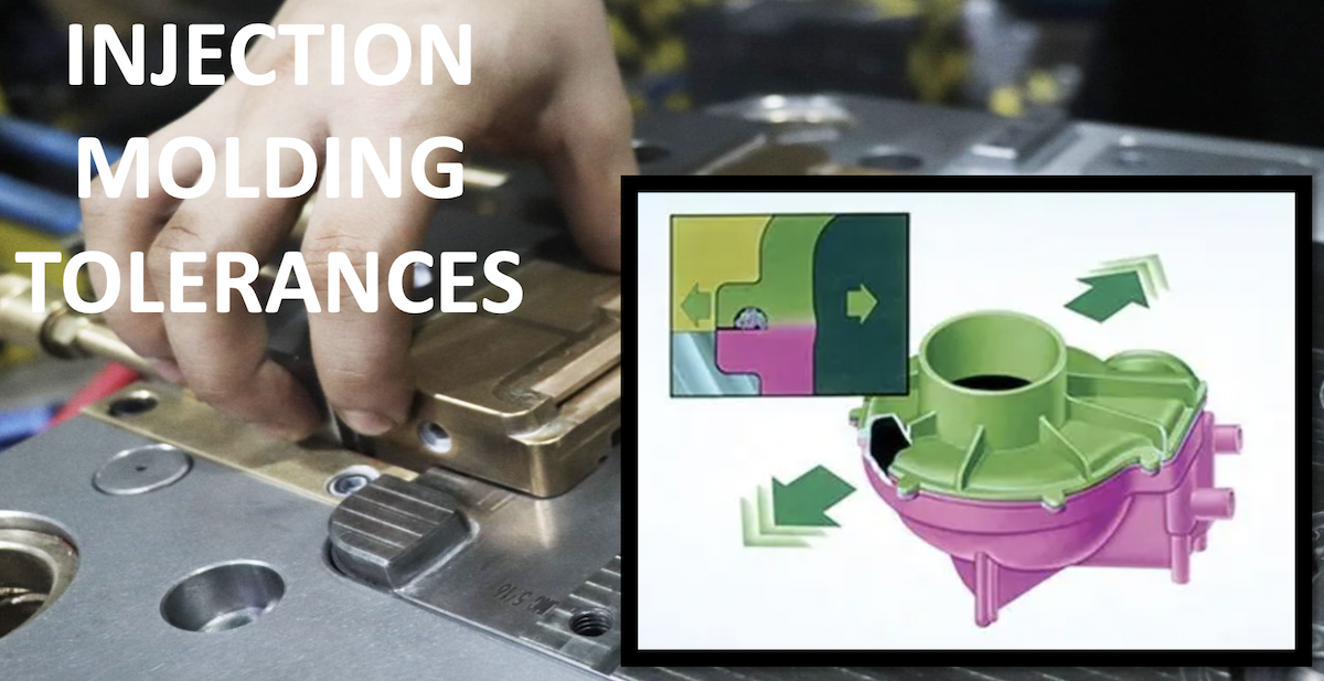
Why Tolerance Matters More Than Most Designers Think
Many designers default to the tightest possible tolerances "just to be safe." In injection molding, this approach is counterproductive.
The Hidden Cost of Over-Tolerancing
Why isn’t ±0.02 mm always "better"? Because plastic behaves differently than metal. Holding a ±0.02 mm tolerance on a large plastic part requires:
- Premium Mold Steel: Hardened steels that can be machined to extreme precision but are brittle and expensive.
- Increased Tooling Lead Time: Tighter tolerances require slower CNC machining, multiple EDM (Electrical Discharge Machining) passes, and extensive mold trial iterations.
- Higher Piece-Part Cost: The molder must run the machine slower, use expensive process monitoring, and scrap a higher percentage of parts that fall out of spec.
Real Examples of Rejected RFQs
We frequently see RFQs rejected or quoted at 3x the expected price because a designer applied a ±0.01 mm tolerance to a non-critical cosmetic wall. At TEAM Rapid, we actively consult with clients to relax non-critical tolerances, often reducing tooling costs by 20% to 40% without compromising the part's function.
What Does "Tolerance" Really Mean in Injection Molding?
To design effectively, engineers must distinguish between different types of variations.
Dimensional vs. Geometric Tolerance
- Dimensional Tolerance: The allowable variation in a specific linear or angular measurement (e.g., a boss diameter of 5.0 mm ±0.1 mm).
- Geometric Tolerance (GD&T): Controls the shape, orientation, and location of features (e.g., flatness, concentricity, true position).
Process Variation vs. Measurement Variation
Molded parts vary from shot to shot (process variation) and from cavity to cavity. Furthermore, measuring soft plastics can induce deflection, leading to measurement variation.
Why Molded Plastic Behaves Differently from Machined Metal
Metal is rigid and cut to size. Plastic is melted, injected under high pressure, and cooled. As it transitions from a molten state to a solid, polymer chains relax and crystallize, causing non-linear shrinkage and internal stresses that metal machining simply does not experience.
Which Tolerance Standards Are Used Worldwide
Relying on a globally recognized standard prevents miscommunication between design and manufacturing teams.
|
Standard |
Primary Use Case |
Advantages |
Limitations |
Preferred Industries |
|
ISO 20457 |
General tolerances for molded plastics |
Globally recognized, easy to apply |
Lacks deep material-specific nuances |
General consumer goods, electronics |
|
DIN 16742 |
Detailed geometric & dimensional tolerances |
Highly detailed, accounts for part size |
Complex to interpret for beginners |
European automotive, precision engineering |
|
SPI / SPE |
US commercial molding guidelines |
Practical, industry-tested in North America |
Less rigorous on geometric controls |
US commercial products, packaging |
|
IATF 16949 |
Automotive quality management |
Ensures high Cp/Cpk process capability |
High documentation and cost overhead |
Automotive tier 1 & 2 suppliers |
|
ISO 13485 |
Medical device manufacturing |
Strict traceability and validation |
Extremely high validation costs |
Medical devices, surgical tools |
What Is a Realistic Injection Molding Tolerance
Instead of blindly quoting a standard, here are practical capability ranges based on decades of tooling experience at TEAM Rapid.
Practical Tolerance Capability Table
|
Feature |
Typical Commercial Capability |
High-Precision Capability |
|
Linear Dimensions |
±0.10 - ±0.30 mm |
±0.05 mm |
|
Hole Diameter |
±0.05 - ±0.15 mm |
±0.03 mm |
|
Wall Thickness |
±10% |
±5% |
|
Flatness |
Depends on geometry & cooling |
0.1 mm per 100 mm length |
|
Roundness/Cylindricity |
Material & geometry dependent |
±0.05 mm on small bores |
Note: High-precision capabilities require optimized mold design, scientific molding, and premium materials.
Part Size vs. Achievable Tolerance
Tolerance is not a static number; it scales with part size. Holding ±0.05 mm on a 10 mm feature is standard. Holding ±0.05 mm on a 500 mm automotive bumper is physically impossible due to cumulative thermal shrinkage. Rule of thumb: Add ±0.01 mm to your tolerance for every additional 100 mm of part length.
The Seven Biggest Factors That Affect Molded Part Tolerance
Competitor articles often only mention material. In reality, tolerance is a systemic outcome.
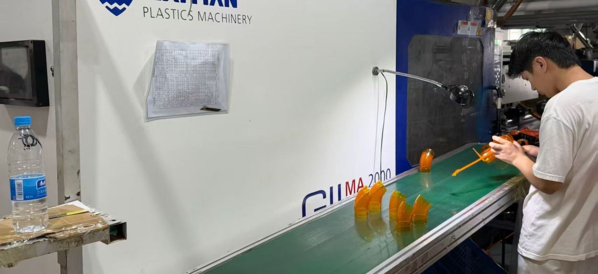
1. Material Shrinkage (The Biggest Variable)
Different polymers shrink at vastly different rates. Amorphous plastics shrink less and more predictably than semi-crystalline plastics.
|
Material |
Typical Shrinkage Rate (%) |
Dimensional Stability |
|
ABS |
0.4% - 0.7% |
Good |
|
PC (Polycarbonate) |
0.5% - 0.7% |
Excellent |
|
PP (Polypropylene) |
1.0% - 2.5% |
Poor (High shrinkage) |
|
PA (Nylon) |
0.5% - 1.5% (up to 3% if wet) |
Fair (Moisture sensitive) |
|
POM (Acetal) |
2.0% - 3.5% |
Good (but high shrinkage) |
|
PEEK |
1.1% - 1.5% |
Excellent (High temp stability) |
|
Glass-Filled (Any) |
0.1% - 0.5% |
Outstanding (Highly rigid) |
2. Part Geometry and Wall Thickness
Thick walls cool slower than thin walls, causing sink marks, voids, and warpage. Uniform wall thickness is the golden rule of injection molding DFM.
3. Mold Design and Cooling
Poorly designed cooling channels lead to uneven cooling. If one side of the mold is hotter, the part will warp toward the hotter side as it shrinks unevenly.
4. Gate Location and Size
The gate is where plastic enters the cavity. High pressure near the gate causes "over-packing" (larger dimensions), while the end of the fill experiences lower pressure (smaller dimensions).
5. Processing Parameters
Melt temperature, injection speed, holding pressure, and cooling time directly dictate final dimensions. Scientific molding locks these parameters in to ensure repeatability.
6. Material Moisture and Conditioning
Hygroscopic materials like Nylon (PA) and PC absorb moisture from the air, which alters their dimensions and mechanical properties post-molding.
7. Machine Capability and Wear
An older toggle machine will not hold the same tolerances as a modern all-electric injection molding machine with closed-loop process control.
GD&T Guidance and Common DFM Mistakes
GD&T for Injection Molded Components
- Avoid over-constraining: Do not apply tight true-position tolerances to features that do not mate with other parts.
- Use functional datums: Base your GD&T datums on how the part is actually assembled in the final product, not how it sits in the mold.
- Profile over flatness: For complex contoured surfaces, use a profile of a surface control rather than trying to map flatness.
Common Engineering Mistakes to Avoid
-
Applying metal tolerances to plastic: Designing a plastic part with the same ±0.01 mm tolerances used for aluminum CNC parts.
-
Ignoring draft angles: Failing to add draft (typically 1° to 2°) causes drag marks, ejection issues, and dimensional distortion.
-
Sharp internal corners: Sharp corners create stress concentrators and hinder plastic flow, leading to warpage. Always use generous fillets.
Scientific Molding and Process Capability (Cp/Cpk)
Achieving tight tolerances in mass production requires moving from "trial and error" to Scientific Molding.
- Cooling Optimization: Using Moldflow analysis to design conformal cooling channels that ensure uniform heat extraction.
- Cavity Pressure Sensors: Installing sensors inside the mold cavity to monitor actual plastic pressure, rather than relying solely on machine hydraulic pressure.
- Process Capability Studies (Cp/Cpk): For critical dimensions, we calculate Cpk. A Cpk of >1.33 indicates the process is capable of holding the tolerance with minimal defect rates.
- First Article Inspection (FAI): A comprehensive dimensional check of the first parts off the production line using CMM (Coordinate Measuring Machines) to validate the mold against the 3D CAD model.
Tolerance Stack-Up in Plastic Assemblies
When multiple molded parts assemble together, individual part tolerances accumulate. This is known as Tolerance Stack-Up.
Where Stack-Up Causes Failures
- Snap-fits and Hinges: Accumulated error can result in snap-fits that are too loose (rattling) or too tight (breaking during assembly).
- Multi-part Housings: Gaps or misalignments in consumer electronics enclosures.
- Threaded Assemblies: Plastic threads are highly susceptible to cross-threading if stack-up errors misalign the boss.
A Simple Stack-Up Calculation Example
Imagine an assembly with Part A (50 mm ±0.2), Part B (30 mm ±0.2), and a required air gap of 2 mm ±0.1 inside a housing of 82 mm ±0.2.
- Max assembly size: 50.2 + 30.2 + 2.1 = 82.5 mm.
- Min housing size: 81.8 mm.
- Result: The parts will not fit.
- Solution: Use RSS (Root Sum Square) statistical tolerancing rather than worst-case arithmetic, or loosen the non-critical housing tolerance.
Secondary Processes Used When Injection Molding Alone Isn't Accurate Enough
Many engineers don't realize that injection molding can be combined with secondary operations to achieve metal-like precision on critical features.
When should you use secondary processes?
- CNC Machining: Used for milling critical mating surfaces or cutting tight-tolerance slots post-molding.
- Reaming & Precision Boring: Used to size internal bores for press-fit metal pins or bearings.
- Grinding: Rarely used for plastics, but applicable to high-performance polymers like PEEK for ultra-flat sealing surfaces.
- Ultrasonic Machining & Laser Trimming: Used to cleanly cut gates or trim flash from complex geometries without inducing mechanical stress.
- Assembly Fixtures: Custom jigs used to hold parts in their nominal shape while adhesives cure or ultrasonic welds are applied, locking in the correct dimensions.
Injection Molding Tolerance FAQ
What is the standard tolerance for injection molding?
For general commercial parts, a standard tolerance is ±0.1 mm to ±0.3 mm for linear dimensions, depending on the part size and material.
Can injection molding achieve ±0.01 mm?
Yes, but only on very small features (under 10 mm), using high-precision materials (like glass-filled LCP or PEEK), high-end electric machines, and secondary CNC machining. It is not feasible for large parts.
What tolerance does ISO 20457 specify?
ISO 20457 provides general tolerance grades (similar to ISO 2768 for metals) based on the nominal size of the feature and the chosen tolerance class (fine, medium, coarse).
Why does plastic shrink after molding?
Plastic shrinks due to thermal contraction as it cools from a molten state to a solid state. Semi-crystalline plastics also shrink due to the densification of polymer chains as they crystallize.
What is the tightest achievable tolerance?
With scientific molding and premium tooling, ±0.025 mm to ±0.05 mm is generally the tightest realistic limit for standard injection molded plastics.
How does temperature affect molded part dimensions?
Plastics have a high Coefficient of Thermal Expansion (CTE). A part measured at 20°C will physically expand if used in a 60°C environment, which must be accounted for in the design phase.
Can glass-filled plastics improve tolerance stability?
Yes. Adding glass fibers (e.g., 30% GF) significantly reduces shrinkage, lowers the CTE, and increases rigidity, making the part much more dimensionally stable.
When should I machine an injection molded part?
You should use secondary CNC machining when a specific feature (like a bore hole or mating flange) requires a tolerance tighter than ±0.05 mm, which is too risky or expensive to achieve directly in the mold.
How are molded parts inspected?
Standard parts are checked with calipers and micrometers. High-precision or complex geometric parts are inspected using CMM (Coordinate Measuring Machines), optical comparators, or 3D laser scanners.
Is tolerance different for prototype and production molds?
Yes. Rapid prototype molds / rapid tooling (often made of aluminum or soft steel) may have slightly wider tolerances and higher part-to-part variation compared to hardened production steel molds, which are machined to exact final dimensions.
Ready to Optimize Your Part Design
Don't let unrealistic tolerances derail your project budget and timeline. The engineering team at TEAM Rapid specializes in DFM analysis, scientific molding, and high-precision tooling.

Upload your 3D CAD files today for a free DFM review and instant injection molding quote. Let’s build it right, the first time.



 Contact