
Gate Design in Injection Molding: Types, Pros, Cons, Design Guidelines & Applications
In injection molding, the gate is far more than a small opening between the runner system and the mold cavity. It is one of the most critical design decisions that determines whether your final part meets dimensional, cosmetic, and structural requirements. Encompassing 13+ injection molding gate types (edge, fan, tab, pin, submarine, banana, direct sprue, diaphragm, ring, disc, film, hot tip, and valve gates), each with distinct advantages, disadvantages, sizing rules, and location guidelines that directly determine part quality, cosmetic appearance, dimensional accuracy, cycle time, and production cost.
What is an injection molding gate? It is the controlled restriction point where molten plastic enters the mold cavity. Despite its small size, the gate governs the entire filling behavior of the part.
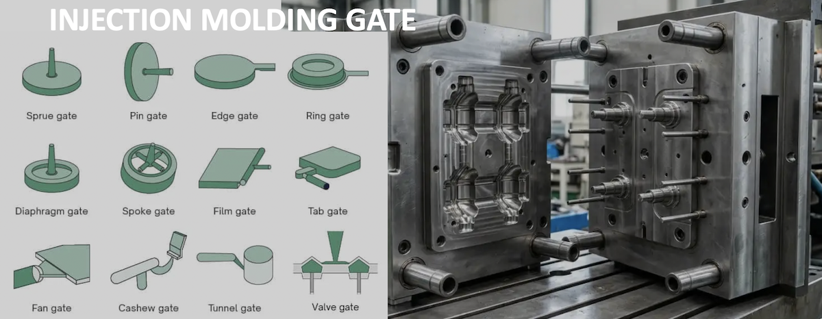
Gate design directly influences:
- Plastic flow behavior and filling balance
- Packing pressure and shrinkage compensation
- Cooling efficiency and cycle time
- Warpage, sink marks, and weld lines
- Air traps and cosmetic quality
- Manufacturing cost and automation potential
At TEAM Rapid, we always recommend addressing gate design during the Design for Manufacturability (DFM) stage-not after mold construction. This allows engineers to optimize part geometry around the gate rather than forcing a gate onto a finalized design.
What Is an Injection Molding Gate
To understand gate design, distinguish between three primary components of the flow system:
|
Component |
Function |
|
Sprue |
Transfers melt from the machine nozzle into the mold |
|
Runner |
Distributes melt from the sprue to individual gates |
|
Gate |
Controls melt entry into the mold cavity |
The flow path: Machine → Sprue → Runner → Gate → Mold Cavity
As melt passes through the gate, several critical phenomena occur:
- Melt acceleration - Velocity increases dramatically due to reduced cross-section
- Shear rate increase - High shear rates (10,000-100,000 s) reduce apparent viscosity
- Pressure drop - Significant pressure loss occurs across the restriction
- Gate freeze-off - The gate solidifies after packing, sealing the cavity
- Packing stage - Additional material flows through the gate to compensate for shrinkage
Why Gate Design Is Critical
Even a perfectly machined mold cannot compensate for poor gate placement. The gate influences:
- Filling pattern - Determines flow front shape and direction
- Packing pressure - Must remain open long enough to transmit pressure
- Fiber orientation - Critical for glass-filled materials
- Residual stress - Undersized gates create high shear and molecular orientation
- Surface finish - Jetting, flow marks, and gate blush originate at the gate
- Weld line position - Gate location determines where flow fronts meet
- Dimensional accuracy - Uneven filling causes differential shrinkage
- Mechanical strength - Weld lines and fiber alignment affect part integrity
- Production efficiency - Gate freeze-off time limits cycle time
Types of Injection Molding Gates
|
Gate Type |
Typical Part Size |
Automation |
Cost |
Common Applications |
|
Edge Gate |
Small to Large |
Manual trimming |
Low |
General purpose, housings |
|
Fan Gate |
Medium to Large |
Manual trimming |
Low-Medium |
Flat panels, automotive |
|
Tab Gate |
Small to Medium |
Manual trimming |
Low |
Optical, cosmetic parts |
|
Pin Gate |
Small to Medium |
Automatic (3-plate) |
Medium |
Multi-cavity, small parts |
|
Submarine Gate |
Small to Medium |
Fully automatic |
Medium |
High-volume consumer parts |
|
Banana Gate |
Small to Medium |
Fully automatic |
Medium-High |
Cosmetic parts, connectors |
|
Direct Sprue Gate |
Medium to Large |
Manual removal |
Low |
Thick parts, large components |
|
Diaphragm Gate |
Medium |
Manual trimming |
Medium |
Cylindrical parts, gears |
|
Ring Gate |
Medium |
Manual trimming |
Medium |
Pipe fittings, housings |
|
Disc Gate |
Small to Medium |
Manual trimming |
Medium |
Medical devices, lenses |
|
Film Gate |
Large |
Manual trimming |
Low-Medium |
Thin-wall, large flat parts |
|
Hot Tip Gate |
Small to Medium |
Fully automatic |
High |
Packaging, automotive |
|
Valve Gate |
Small to Large |
Fully automatic |
Very High |
Automotive, medical, electronics |
Edge Gate
The most common gate type. A rectangular opening at the parting line connecting the runner to the cavity edge.
- Advantages: Simple design, easy to modify, low cost, works with most materials.
- Disadvantages: Visible mark, requires trimming, can cause jetting.
- Design rule: Gate thickness = 50%-75% of part wall thickness. Best for ABS, PP, PE, and general-purpose thermoplastics.
Fan Gate
A wide, flat gate that spreads melt across a broad area, creating a uniform flow front.
- Best for: Flat parts requiring minimal warpage-automotive panels, large covers, and housings. The wide entry reduces molecular orientation and ensures symmetric shrinkage.
Tab Gate
A small extension (tab) protrudes from the part. Melt enters the tab first, then flows into the cavity, preventing jetting.
- Preferred when: The part has a large open cavity immediately after the gate, or for optical/cosmetic parts (PC, PMMA, ABS). The tab is trimmed off, leaving no mark on the part.
Pin Gate
A small circular gate used in three-plate molds for automatic runner separation.
- Advantages: Small vestige (0.5-1.5 mm), automatic degating, excellent for multi-cavity molds.
- Limitations: Requires three-plate mold (higher cost), limited packing effectiveness, not suitable for large parts.
Submarine (Tunnel) Gate
An angled gate below the parting line that shears off automatically during ejection.
- Key benefit: Fully automatic degating-ideal for high-volume production.
- Gate diameter: 0.75-2.0 mm, tunnel angle: 30°-45°.
- Common defects: Gate blush, part deformation during degating, incomplete shearing.
Banana (Cashew) Gate
A curved tunnel gate that enters the cavity at a gradual angle. Similar to submarine gates but with a curved profile that reduces stress concentration and improves surface quality.
- Applications: Connector housings, small cosmetic parts, consumer electronics.
Direct Sprue Gate
Connects the sprue directly to the part without a runner. Lowest pressure drop of all gate types.
- Best for: Thick parts requiring extended packing, transparent products (PC, PMMA), large single-cavity components.
- Drawback: Large gate vestige requiring post-molding removal.
Diaphragm, Ring & Disc Gates
These specialized gates create symmetrical radial flow for cylindrical parts:
- Diaphragm gate - Surrounds the inner diameter; used for gears and bearing housings
- Ring gate - Located on the outer diameter; used for pipe fittings and cylindrical housings
- Disc gate - Central circular gate; used for medical devices requiring concentricity
Film Gate
A wide, thin gate spanning the full part width. Creates a perfectly linear flow front for thin-wall, large-surface parts like automotive trim panels and display covers.
Hot Tip Gate
A thermally gated hot runner system. The gate stays molten via a heated nozzle tip. No runner waste, reduced cycle time, small vestige. Common in packaging, automotive, and high-volume production.
Valve Gate
The most advanced gating solution. A mechanically actuated pin opens and closes the gate with precision.
Benefits:
- No gate vestige (flat, invisible mark)
- Sequential gating eliminates weld lines
- Best cosmetics for Class A surfaces
- Precise fill control
- Applications: Automotive exterior panels, medical devices, electronics housings.
- Cost: 5,000- 15,000 per gate. ROI typically achieved within 6-18 months for high-volume production.
Cold Runner vs Hot Runner Gates
|
Factor |
Cold Runner |
Hot Runner |
|
Initial tooling cost |
Lower |
Higher |
|
Material waste |
High (runner is scrap) |
Minimal to zero |
|
Cycle time |
Longer |
Shorter |
|
Maintenance |
Simpler |
More complex |
|
Part quality |
Good |
Excellent |
|
Automation |
May need runner removal |
Fully automatic |
|
Best for |
Low-medium volume |
High volume |
Recommendation: Choose cold runner for prototypes and low-volume production. Choose hot runner when production exceeds 50,000 parts and material savings justify the investment.
How to Select the Right Gate Type
By Material
|
Material |
Recommended Gates |
Notes |
|
PP, PE |
Edge, submarine, hot tip |
Low viscosity; prone to jetting |
|
ABS |
Edge, fan, tab, pin |
Versatile; most gates work |
|
PC |
Tab, fan, direct sprue, valve |
High viscosity; avoid small gates |
|
PA6, PA66 |
Edge, submarine, pin, hot tip |
Low viscosity; must be dried |
|
POM |
Edge, pin, submarine |
Sensitive to shear heating |
|
PMMA |
Tab, fan, valve |
Optical clarity requires low stress |
|
TPU/TPE |
Edge, fan, valve |
Flexible; difficult to trim |
|
PEEK |
Direct sprue, edge, valve |
Very high temperature processing |
By Part Geometry
- Thin wall (<1 mm): Film gate, fan gate, hot tip
- Thick wall (>3 mm): Direct sprue, large edge gate
- Long flow length: Multiple gates, valve gate
- Cylindrical: Diaphragm, ring, or disc gate
- Flat/large area: Fan gate, film gate, multiple gates
By Cosmetic Requirements
- Visible surfaces (Class A): Valve gate only
- Hidden surfaces: Edge, pin, submarine gate
- Transparent parts: Direct sprue, tab gate, valve gate
By Production Volume
- Prototype (1-1,000): Edge gate, direct sprue
- Low-volume (1,000-50,000): Edge, pin, submarine
- Mass production (>50,000): Hot runner (hot tip or valve gate)
Gate Location Design Guidelines
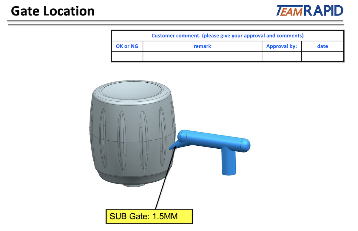
Gate at the Thickest Section
The gate must remain open long enough to transmit packing pressure. Thicker sections cool more slowly, keeping the gate area molten longer. This prevents sink marks, voids, and dimensional inaccuracy.
Shortest Flow Length
Minimize the distance melt travels to fill the cavity. For most materials, the flow length to wall thickness ratio (L/t) should not exceed 100:1 to 150:1.
Balanced Filling
- Single cavity: Place gate at geometric center for symmetrical parts
- Multi-cavity: Use balanced runner systems for simultaneous filling
- Family molds: Adjust gate sizes to balance different part volumes
Avoid Cosmetic Surfaces
Place gates on hidden surfaces (bottom, inside, back). For visible surfaces, use valve gates with sequential filling.
Prevent Weld Lines
Position gates so weld lines form in non-critical areas. Use sequential valve gating to eliminate weld lines entirely.
Reduce Air Traps
Place gates so the flow front pushes air toward vents. Ensure vents are at the end of fill.
Avoid Jetting
Use tab gates or fan gates when the gate opens into a large cavity. Increase gate size to reduce exit velocity.
Control Fiber Orientation
For glass-filled materials (PA GF, PBT GF, PPS GF), gate placement determines fiber orientation and directly affects warpage and mechanical strength. Align fibers in the direction of primary loading.
Gate Size Design Guidelines
|
Parameter |
Guideline |
|
Gate width |
25%-75% of part width at gate location |
|
Gate thickness |
50%-75% of part wall thickness |
|
Gate length |
0.5-1.0 mm (shorter is better) |
|
Freeze-off time |
Proportional to gate thickness? |
Oversized gates cause: extended cycle time, large vestige, possible sink near gate.
Undersized gates cause: short shots, high shear, jetting, premature freeze-off, high residual stress.
Common Gate-Related Defects and Solutions
|
Problem |
Possible Cause |
Gate Solution |
|
Short shot |
Gate too small |
Increase gate thickness; add gates |
|
Sink marks |
Premature freeze-off |
Increase gate thickness; move to thick section |
|
Jetting |
Small gate into open cavity |
Use tab/fan gate; increase size |
|
Burn marks |
Air trapped |
Reposition gate; add vents |
|
Weld lines |
Multiple flow fronts |
Change location; use sequential gating |
|
Warpage |
Asymmetric filling |
Balance gate placement |
|
Gate blush |
High shear stress |
Increase gate size; reduce speed |
|
Excessive vestige |
Gate too large |
Reduce size; use valve gate |
Gate Vestige: Why It Matters
Gate vestige is the mark left where the gate was located.
Different gates leave different marks:
- Valve gate: Flat, nearly invisible
- Hot tip: Small raised nub (0.5-1.5 mm)
- Submarine: Small circular mark on ejector side
- Edge gate: Visible line on part edge
- Direct sprue: Large circular mark (3-8 mm)
By industry:
- Automotive exterior: Zero visible vestige (valve gate only)
- Consumer electronics: Minimal vestige on visible surfaces
- Medical: No sharp edges, minimal vestige
- Industrial: Functional vestige acceptable
Methods to reduce gate marks: Valve gates, optimized gate sizing, hidden gate placement, post-molding trimming, process optimization.
Multi-Gate Design
Multiple gates are necessary when:
- Flow length exceeds material limits
- Parts are larger than 200-300 mm
- Thin walls freeze too quickly for single-gate filling
- Warpage control requires balanced filling
- Weld line elimination is needed (sequential valve gating)
Advantages: Reduced flow length, lower injection pressure, better dimensional control, reduced clamping force, faster filling.
Key consideration: All gates must be balanced (same size and runner length) unless sequential gating is intentionally used to control flow front progression.
Conclusion
Gate design is one of the most critical-and most often underestimated-aspects of plastic injection molding engineering. The right gate type, size, and location can mean the difference between a perfect part and costly failures.

At TEAM Rapid, we approach gate design as a fundamental part of our DFM process. Our engineers evaluate gate options during the earliest stages of mold design, considering material properties, part geometry, cosmetic requirements, production volume, and automation needs.
Whether you need a simple edge gate for a prototype or a sophisticated sequential valve gate system for automotive production, our team delivers the right solution.
Ready to optimize your gate design? Contact us for a free DFM analysis and gate design consultation.
FAQ
Q: What is the most common gate type in injection molding?
A: The edge gate-due to its simplicity, low cost, and versatility with most materials.
Q: How do I choose between hot runner and cold runner?
A: Hot runners are justified for high-volume production (>50,000 parts) where material savings and cycle time reduction offset higher tooling cost.
Q: What gate type leaves the smallest mark?
A: Valve gates leave the flattest, least visible mark-often nearly invisible on Class A surfaces.
Q: How does gate size affect cycle time?
A: Larger gates take longer to freeze off, extending cycle time. Smaller gates freeze faster but may not allow adequate packing.
Q: Can gate location cause warpage?
A: Yes. Asymmetric gate placement creates uneven filling and packing, leading to differential shrinkage and warpage.


 Contact