
How to Prevent Sink Marks in Thick-Walled Injection Molded Parts
Injection molding sink marks in thick walls are a common cosmetic and functional defect in production. They show up as localized depressions on the surface opposite thick features, including bosses, ribs, and intersecting walls. The underlying cause is differential shrinkage. Thick sections cool and solidify more slowly than the surrounding material, leaving a volume deficit that pulls the surface inward. The most effective way to prevent sink marks in thick-walled injection molded parts is to minimize wall thickness variation during part design, ensure balanced mold cooling near thick features like bosses and ribs, and optimize packing pressure and hold time to compensate for volumetric shrinkage before the gate freezes.
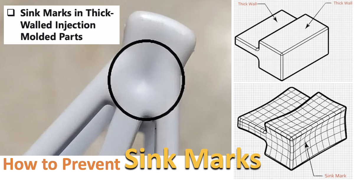
A Design and Cooling Problem Leads to Sink Marts in Thick-Walled Parts
When sink marks appear, teams often start by increasing packing pressure or extending hold time. Those changes can help, but they rarely solve the problem on their own. In most cases, the underlying issue is part geometry: thick sections hold more heat and cool at a different rate than nearby thin walls.
The outer skin may solidify while the core is still molten and shrinking. If enough material is not packed into the area before the gate freezes, the surface can pull inward. That is why sink marks may remain even after extensive process adjustments.
The best place to start is during part design. Reduce wall-thickness variation, refine feature geometry, and plan cooling around thick sections to address the cause rather than the symptom. Use process adjustments to fine-tune the result, not as the primary fix.
Part Design Strategies to Minimize Sink Marks
Aim for uniform wall thickness throughout the part. Where thickness changes cannot be avoided, use gradual transitions—typically a 3:1 taper ratio between thick and thin sections.
If a feature must remain thick, consider coring out its interior. For example, a cored boss can retain the outer geometry needed for assembly while reducing the effective cross-section. That leaves less material to shrink during cooling.
- Keep rib thickness at or below 60% of the adjacent nominal wall thickness.
- The boss outer diameter should be no more than twice the nominal wall thickness.
These ratios help limit the local thermal mass that drives differential shrinkage. Refer to the page for more ribs and bosses design guides.
Structural Components with Thick Bosses and Mounting Features
Bosses and mounting features must resist loads while meeting stiffness and dimensional requirements, all without creating sink marks. A boss that is too thin may strip threads or crack under load; one that is too thick can cause sink marks.
A common approach is to core the boss so the wall thickness around the fastener hole stays uniform. Add gussets or ribs at the base to transfer loads into the surrounding structure instead of relying on a thick boss. This supports mechanical performance while reducing the thermal mass that causes sink.
For mounting features that interface with metal inserts or ultrasonic welding horns, check the material supplier's design guidelines. Insert-molded bosses may need different wall-thickness ratios than bosses designed for self-tapping screws.
Mold Design and Cooling Strategies for Thick-Walled Parts
Even a well-designed part can develop sink marks if the mold does not remove heat evenly from thick sections. Cooling-channel layout is one of the most influential mold-design factors in sink-mark control.
Straight-through cooling channels can leave hot spots beneath bosses and rib intersections. These areas solidify more slowly, giving shrinkage more time to deform the surface.
Conformal cooling channels, baffles, and bubblers can bring coolant closer to thick features. The aim is to balance cooling across the part so one area does not remain molten much longer than the surrounding material.
Running Mold Flow Analysis before making tooling changes can help identify hot spots early. Simulation can show where packing pressure drops, where cooling falls short, and where sink marks are likely to develop. That makes it easier to target corrections instead of relying on trial-and-error mold changes.
Improve Cooling Near Thick Features
Place cooling channels as close to thick features as practical, while maintaining adequate mold strength. As a general guideline, keep the channel centerline one to two channel diameters from the cavity surface.
Where straight channels cannot reach bosses or rib intersections, consider thermal pins or high-conductivity inserts, such as beryllium copper, to draw heat away from the thick section. These passive solutions can be cost-effective for low- to medium-volume molds.
Check cooling performance by measuring the part's surface temperature at several points immediately after ejection. A difference greater than 10°C between thick and thin areas indicates that cooling may be unbalanced.
Evaluate Mold Temperature Control and Cooling Time
Consistent mold temperature supports repeatable dimensions. Even a small temperature fluctuation can shift the solidification front and change how much shrinkage occurs before the gate freezes.
Use a dedicated mold-temperature controller with closed-loop feedback rather than relying only on shop chilled water. For semi-crystalline materials such as nylon and POM, mold temperature affects crystallinity and, in turn, the amount of shrinkage.
Set cooling time according to the thickest section, not the nominal wall thickness. One starting point is to calculate cooling time with the one-dimensional heat-conduction equation for the maximum wall thickness, then add a 10–20% safety margin. If cooling time is too short, the part may continue shrinking after ejection and develop post-molding warpage as well as sink marks.
Process Parameter Adjustments for Sink Mark Prevention
Once part design and cooling are in good shape, process settings provide the final level of control. Focus on packing pressure, packing time, and gate freeze-off.
Increase packing pressure in 5–10 MPa increments and track part weight.
When the weight levels off, the cavity is fully packed; further pressure increases are unlikely to reduce sink marks. Excessive packing can cause flash, residual stress from over-packing, or ejection problems.
Extend packing time until the gate freezes.
Extra hold time will not help if the gate has already frozen. To check gate freeze, weigh parts at progressively longer hold times. When part weight stops increasing, the gate has sealed.
Melt temperature and injection speed also affect the result.
A slightly higher melt temperature can improve pressure transmission into thick sections, but it can also increase overall shrinkage. Find the right balance through a structured design of experiments (DOE), rather than changing one setting without a plan.
A Step-by-Step Troubleshooting Workflow for Sink Marks
When sink marks show up in production, a consistent troubleshooting sequence can save time and avoid unnecessary tooling changes.
Step 1: Confirm the defect is a sink mark.
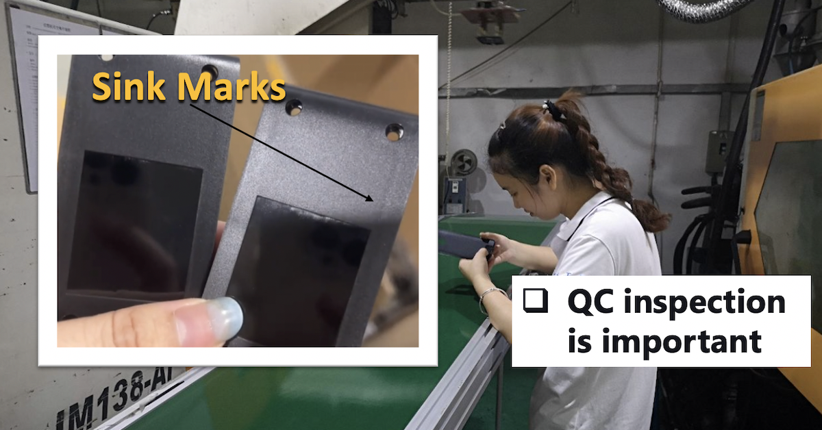
Visually inspect the affected area. Sink marks are usually smooth, shallow depressions opposite thick features. Flow lines, weld lines, or voids may point to a different root cause.
Step 2: Check part design.
Measure wall thickness where the sink appears and compare it with nearby areas. If the ratio is greater than 1.5:1, a design change is the most reliable long-term fix.
Step 3: Evaluate cooling balance.
Measure mold-surface temperature at the sink location and at a reference area with a thin wall. A significant difference points to a cooling issue. Review the channel layout and consider adding baffles or thermal pins.
Step 4: Optimize packing.
Increase packing pressure and time in controlled increments, weighing parts after each change. If sink marks remain after confirming gate freeze, the problem is likely geometric or thermal rather than a lack of packing.
Step 5: Run mold flow simulation.
If the steps above do not resolve the issue, a mold flow analysis can help reveal interactions among the filling pattern, packing distribution, and cooling that are difficult to diagnose through trials alone.
Step 6: Implement and verify.
After making changes, run at least 30 consecutive shots and measure the affected dimension or surface profile. Record the results to establish a new process baseline.
Table for the Workflow
Step
Action
What to Do
Key Indicator / Outcome
1
Confirm the defect
Visually inspect the affected area. Sink marks appear as smooth, shallow depressions opposite thick features.
If you see flow lines, weld lines, or voids instead, the root cause may be different.
2
Check part design
Measure wall thickness at the sink location and compare it with adjacent areas.
If the thickness ratio exceeds 1.5:1, a design change is the most reliable long-term fix.
3
Evaluate cooling balance
Measure mold-surface temperature at the sink location and at a reference thin-wall area.
A significant temperature difference indicates a cooling issue. Review channel layout; consider adding baffles or thermal pins.
4
Optimize packing
Increase packing pressure and time in controlled increments. Weigh parts after each change.
If sink persists after confirming gate freeze, the problem is geometric or thermal—not a packing deficiency.
5
Run mold flow simulation
Perform a mold flow analysis to reveal interactions among filling pattern, packing distribution, and cooling.
Identifies issues that are difficult to diagnose through physical trials alone.
6
Implement and verify
Run at least 30 consecutive shots after making changes. Measure the affected dimension or surface profile.
Record results to establish a new process baseline.
Low-Volume Production vs. High-Volume Production
The cost-benefit trade-off for preventing sink marks differs between short production runs and high-volume programs.
- For low-volume production—hundreds to a few thousand parts—process optimization and small mold changes often provide the quickest return. Adjusting packing pressure, extending cooling time, or adding a temporary baffle may resolve sink marks without a major capital investment.
- For high-volume production—from tens of thousands to millions of parts—design improvements and conformal cooling can pay off through shorter cycles, less scrap, and fewer quality escapes. On a million-part run, cutting cycle time by two seconds can save substantial machine time.
Purchasing teams and company founders should compare the per-part cost of a design change with the cumulative cost of compensating through the process. A one-time tooling modification may eliminate a recurring adjustment that adds cost and variability to every shot.
Frequently Asked Questions About Injection Molding Sink Marks
Q: Can sink marks be completely eliminated?
A: In most cases, sink can be reduced to a level below visible or functional limits, but zero shrinkage is physically impossible. The goal is to keep surface deviation within the specified cosmetic or dimensional tolerance.
Q: Does material selection affect sink marks?
A: Yes. Semi-crystalline materials such as nylon, POM, and PBT generally shrink more than amorphous materials such as ABS, PC, and PMMA, so they may be more prone to sink. Filled grades, including glass-fiber- and mineral-filled materials, generally shrink less and resist sink better than unfilled grades.
Q: Will increasing packing pressure always fix sink?
A: No. If the gate freezes before the thick section solidifies, additional packing pressure cannot reach the shrinking material. Packing helps only while the gate remains open and material can still enter the cavity.
Q: How do I know if my sink mark is a design problem or a process problem?
A: If sink persists across a broad process window—including changes to pressure, temperature, and cooling time—the cause is likely geometric. If moderate process changes eliminate it, the process was probably not optimized.
Q: Can post-molding operations hide sink marks?
A: Painting, texturing, or pad printing may hide shallow sink marks cosmetically, but they do not correct the underlying shrinkage. For functional surfaces or tight-tolerance interfaces, prevention during design and mold development is the more reliable approach.
Conclusion
Injection molding sink marks in thick walls are best addressed through sound part design, targeted mold cooling, and disciplined process control. Treating sink as a machine-setting issue alone can lead to endless parameter changes and inconsistent results. Addressing the thermal and geometric causes early helps reduce scrap, save time, and produce parts that meet cosmetic and dimensional requirements.
If you are developing a new part or troubleshooting an existing design, reviewing the geometry and manufacturing requirements with an experienced injection molding partner can help identify sink risks before production. TEAM Rapid's injection molding services include design-for-manufacturability feedback, mold flow simulation, and production support to help move projects from concept to production with fewer iterations.



 Contact