
Injection Molding Tolerances by Material: Amorphous vs. Semi-Crystalline Plastics
Injection molding tolerances are important when manufacturing plastic components that require accurate dimensions, reliable assembly, and consistent performance. However injection molding tolerances vary by material, with amorphous plastics generally offering tighter and more stable dimensional tolerances, while semi-crystalline plastics require wider tolerances due to greater and more variable shrinkage during cooling.
For example: materials such as ABS and PC generally have more predictable shrinkage behavior, while nylon (PA), PBT, POM, and PP can experience greater dimensional changes due to crystallization and other material characteristics. Material structure, shrinkage characteristics, cooling behavior, and moisture absorption can all affect the final dimensions of molded parts too.
Understanding injection molding tolerances by material helps product designers and manufacturing engineers establish realistic drawing requirements, select suitable resins, and avoid costly tooling modifications.
In this article, we explain the differences between amorphous and semi-crystalline plastics, compare the tolerance considerations of commonly used injection molding materials, and discuss how mold design and process control affect dimensional accuracy.
What Are Injection Molding Tolerances
Injection molding tolerances refer to the acceptable dimensional variations of a molded plastic component compared with its specified dimensions on an engineering drawing.
For example, if a plastic component has a specified dimension of 20.00 ± 0.20 mm, the acceptable dimensional range is 19.80–20.20 mm.
Unlike CNC-machined metal components, injection molded plastic parts can experience dimensional changes during cooling, solidification, and subsequent conditioning. These changes are influenced by material properties, mold design, processing conditions, and part geometry.
Therefore, manufacturers need to consider the behavior of the selected plastic material when designing injection molds and establishing dimensional requirements.
Dimensional Tolerances vs. Geometric Tolerances
Dimensional tolerances control the acceptable variation in individual measurements, such as length, width, height, diameter, and wall thickness.
Geometric tolerances, commonly specified through GD&T (Geometric Dimensioning and Tolerancing), control the form, orientation, and position of features.
Common examples include:
- Flatness: Controls how much a surface can deviate from a perfectly flat plane.
- Position: Controls the location of holes, pins, and other features relative to specified datums.
- Perpendicularity: Controls the angular relationship between two surfaces or features.
- Parallelism: Controls how parallel two surfaces or features must remain.
- Concentricity or runout: Controls the alignment of circular features where required.
For injection molded components, both dimensional and geometric tolerances are important. A part may meet its specified length and width but still fail during assembly because of warpage or an incorrectly positioned mounting hole.
Why Are Injection Molding Tolerances Important
Dimensional accuracy directly affects the functionality and assembly of plastic components.
For example, an automotive connector housing may require accurate hole positions and internal dimensions to ensure that electrical terminals fit correctly. A plastic gear may require controlled dimensions to maintain proper engagement with other mechanical components.
If tolerances are too loose, parts may not fit or function correctly. If tolerances are unnecessarily tight, tooling costs, inspection requirements, and production scrap rates may increase.
The goal is to establish tolerances that meet functional requirements while remaining practical for injection molding production.
Common Standards for Injection Molded Part Tolerances
ISO 20457 is an important international standard covering dimensional and geometrical tolerances and acceptance conditions for plastic molded parts.
The latest edition, ISO 20457:2026, was published in August 2026, replacing the previous 2018 edition.
The standard provides guidance on general tolerances, individually specified tolerances, and technically achievable accuracy for plastic molded components.
It also recognizes that plastic materials behave differently from metals because of shrinkage, deformation, anisotropic behavior, and processing-related dimensional changes.
When specifying injection molding tolerances, engineers should consider the applicable standard, the functional requirements of the component, and the actual manufacturing capabilities.
Amorphous vs. Semi-Crystalline Plastics: How Material Structure Affects Tolerances
Plastic materials are generally divided into two main categories based on their molecular structure: amorphous and semi-crystalline plastics.
This distinction is important because the two material groups behave differently during injection molding, particularly during cooling and solidification.
Injection Molding Tolerances for Amorphous Plastics
Amorphous plastics have randomly arranged molecular chains without a defined crystalline structure. Common amorphous injection molding materials include:
- ABS (Acrylonitrile Butadiene Styrene)
- PC (Polycarbonate)
- PMMA (Acrylic)
- PS (Polystyrene)
- PVC (Polyvinyl Chloride)
These materials generally have relatively low and more predictable molding shrinkage compared with many semi-crystalline plastics.
As a result, amorphous materials can often provide better dimensional consistency when the mold design and injection molding process are properly controlled.
However, this does not mean that amorphous plastics always achieve tighter tolerances. For example, PC components can experience residual stress, while large ABS housings may develop warpage due to uneven wall thickness and cooling. Part geometry and processing conditions remain important.
Injection Molding Tolerances for Semi-Crystalline Plastics
Semi-crystalline plastics contain both crystalline and amorphous regions in their molecular structure. Common materials include:
- PA6 and PA66 (Nylon)
- PBT (Polybutylene Terephthalate)
- POM (Polyoxymethylene)
- PP (Polypropylene)
- PE (Polyethylene)
- PET (Polyethylene Terephthalate)
During cooling, crystalline regions form and develop within the material. This crystallization process contributes to volume changes and molding shrinkage.
Compared with amorphous plastics, semi-crystalline materials generally have higher shrinkage and may show greater dimensional variation.
Their shrinkage can also be affected by mold temperature, cooling time, material grade, packing pressure, and fiber orientation.
For example, nylon components can change dimensions after absorbing moisture, while glass-fiber-reinforced PBT may experience different shrinkage rates in the flow and cross-flow directions.
These characteristics make dimensional control more challenging, particularly for precision components.
Amorphous vs. Semi-Crystalline Plastics: Key Differences
|
Characteristics |
Amorphous Plastics |
Semi-Crystalline Plastics |
|
Molecular structure |
Random molecular arrangement |
Partially crystalline structure |
|
Typical shrinkage |
Relatively low |
Generally higher |
|
Shrinkage behavior |
Often more predictable |
More affected by crystallization |
|
Warpage risk |
Depends on geometry and cooling |
Can be significant due to directional shrinkage |
|
Moisture sensitivity |
Generally lower |
Material-dependent; nylon is particularly sensitive |
|
Dimensional stability |
Often easier to control |
Requires careful material and process control |
|
Common materials |
ABS, PC, PMMA, PS |
PA, PBT, POM, PP, PE |
The table provides a general comparison rather than a guarantee of manufacturing accuracy. Different resin grades, fillers, reinforcement materials, and part designs can produce significantly different results.
Injection Molding Tolerances by Material: Typical Values and Considerations
Different plastic materials have different shrinkage rates and dimensional characteristics during injection molding. Understanding these differences is essential when designing injection molds and establishing realistic dimensional tolerances.
As a general rule, amorphous plastics such as ABS and PC have relatively low molding shrinkage, while semi-crystalline plastics such as nylon, PBT, POM, and PP generally have higher shrinkage.
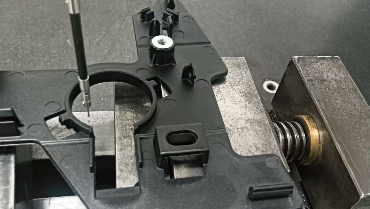
The following table provides typical molding shrinkage ranges for commonly used injection molding materials. These values are useful for preliminary mold design and material comparison, but the actual shrinkage should be confirmed using the specific resin manufacturer's data sheet.
Typical Injection Molding Shrinkage Rates by Material
|
Material |
Plastic Type |
Typical Mold Shrinkage |
|
ABS |
Amorphous |
0.4–0.7% |
|
PC |
Amorphous |
0.5–0.7% |
|
PC/ABS |
Amorphous blend |
0.4–0.7% |
|
PMMA |
Amorphous |
0.2–0.6% |
|
PS |
Amorphous |
0.3–0.6% |
|
PA6 (Nylon 6) |
Semi-crystalline |
0.7–1.5% |
|
PA66 (Nylon 66) |
Semi-crystalline |
0.8–1.8% |
|
PA6 + 30% GF |
Semi-crystalline, reinforced |
0.3–0.8% |
|
PA66 + 30% GF |
Semi-crystalline, reinforced |
0.3–1.0% |
|
PBT |
Semi-crystalline |
1.5–2.2% |
|
PBT + 30% GF |
Semi-crystalline, reinforced |
0.3–1.0% |
|
POM (Acetal) |
Semi-crystalline |
1.8–2.5% |
|
PP |
Semi-crystalline |
1.0–2.5% |
|
HDPE |
Semi-crystalline |
1.5–4.0% |
|
LDPE |
Semi-crystalline |
1.5–5.0% |
|
PET |
Semi-crystalline |
1.2–2.0% |
Important: These are indicative reference ranges, not guaranteed values for every resin grade. Glass-fiber content, wall thickness, flow direction, mold temperature, holding pressure, and cooling conditions can significantly change actual shrinkage. Some reinforced grades may also have different shrinkage in the flow and cross-flow directions.
Typical Dimensional Tolerance Ranges for Injection Molded Parts
Molding shrinkage and dimensional tolerance are two different concepts.
For example, if a material has a shrinkage rate of 0.5%, a 100 mm mold dimension does not automatically mean the finished part will have a ±0.5 mm tolerance.
Shrinkage determines the expected dimensional contraction, while tolerance determines the acceptable variation around the specified finished-part dimension.
For preliminary engineering discussions, the following values can be used as practical planning examples:
|
Part Dimension |
General Tolerance Planning Range |
Tighter Tolerance Target |
|
1–10 mm |
±0.05–0.15 mm |
±0.03–0.05 mm |
|
10–30 mm |
±0.10–0.20 mm |
±0.05–0.10 mm |
|
30–100 mm |
±0.15–0.30 mm |
±0.10–0.15 mm |
|
100–200 mm |
±0.20–0.50 mm |
±0.15–0.25 mm |
|
Over 200 mm |
±0.30–0.80 mm or more |
Requires project-specific evaluation |
These ranges are preliminary manufacturing guidelines, notuniversal material-specific capabilities or ISO 20457 tolerance grades. Actual achievable tolerances must be evaluated according to the material, nominal dimension, part geometry, mold construction, process stability, and inspection conditions.
For example, a small ABS component with uniform wall thickness may be easier to hold to a tight tolerance than a large nylon component with complex geometry and moisture-sensitive dimensions.
ISO 20457 provides a more structured approach to defining tolerances for plastic molded parts. Its tolerance grades consider nominal dimensions and whether features are tool-specific or non-tool-specific.
Key Material Considerations
ABS and PC: These amorphous plastics generally offer relatively low and predictable shrinkage. However, uneven cooling, residual stress, and wall thickness variations can still cause dimensional problems.
Nylon (PA6 and PA66): Nylon has higher shrinkage and absorbs moisture, which can change part dimensions after molding. Glass-fiber reinforcement reduces overall shrinkage but may introduce directional shrinkage.
PBT: PBT has relatively high shrinkage due to crystallization. Glass-fiber reinforcement can reduce shrinkage, but fiber orientation and cooling conditions must be considered.
POM, PP, and PE: These semi-crystalline plastics generally have higher shrinkage. Uniform wall thickness, proper gate positioning, and controlled cooling are important for reducing warpage and dimensional variation.
PMMA: PMMA generally has relatively low and predictable shrinkage, making it suitable for transparent components requiring good dimensional consistency. Residual stress still needs to be controlled.
Factors That Affect Injection Molded Part Tolerances
Material selection is important, but it is not the only factor determining injection molding tolerances.
Two components made from the same plastic material can have very different dimensional accuracy because of differences in geometry, mold design, and processing conditions.
Material Shrinkage and Mold Shrinkage Compensation
Plastic materials shrink as they cool and solidify inside the mold. To achieve the required final dimensions, mold cavities must be designed to account for the expected shrinkage.
For example, if a plastic component needs to have a final dimension of 100 mm, the corresponding mold dimension will generally need to be larger to compensate for shrinkage. However, shrinkage is not always uniform.
It can vary depending on:
- Resin grade and material supplier.
- Glass-fiber or mineral filler content.
- Material flow direction.
- Wall thickness.
- Mold temperature.
- Packing pressure.
- Cooling time.
For semi-crystalline materials such as nylon, PBT, and POM, crystallization also affects shrinkage. Therefore, manufacturers should not rely only on a general material shrinkage value when designing precision injection molds.
Material data sheets provide useful starting information, but actual shrinkage should be evaluated based on the selected grade, component geometry, and molding conditions.
Part Geometry and Wall Thickness
Part geometry has a direct influence on dimensional accuracy. Components with uniform wall thickness are generally easier to control than parts with significant thickness variations. When a part has thick and thin sections, these areas may cool at different rates. This can lead to differential shrinkage, sink marks, and warpage.
Other geometry-related factors include:
- Long and thin sections.
- Large flat surfaces.
- Deep ribs and bosses.
- Uneven material distribution.
- Complex internal features.
- Large distances between critical dimensions.
For example, a long plastic housing may experience dimensional changes along its length, even when its individual wall thicknesses are relatively uniform.
Designers should avoid unnecessary wall thickness changes and consider the effects of ribs, bosses, and other structural features during the initial design stage.
Mold Design and Mold Steel Selection
Injection mold quality plays an important role in achieving consistent dimensions.
The mold must be designed around the selected material, part geometry, shrinkage characteristics, and production requirements.
Important considerations include:
-
Cavity and Core Dimensions
Mold cavities and cores must account for material-specific shrinkage. Incorrect compensation can cause consistent dimensional deviations in the molded components.
-
Cooling System Design
Uniform cooling helps reduce differences in shrinkage between different areas of a component. Poorly designed cooling channels may create temperature variations across the mold, resulting in warpage and dimensional inconsistency.
-
Gate Location
Gate location influences material flow, packing, and fiber orientation. For glass-fiber-reinforced nylon and PBT, gate positioning is particularly important because fiber orientation can affect directional shrinkage.
-
Mold Steel Selection
Mold steel should be selected according to production volume, material characteristics, tooling requirements, and expected mold life.
Common mold steels include P20, H13, NAK80, and S136. The choice of mold steel alone does not determine dimensional accuracy. Proper machining, mold assembly, cavity finishing, and ongoing maintenance are also essential.
Injection Molding Process Parameters
Even a well-designed mold can produce dimensional variations if processing conditions are inconsistent.
Important injection molding parameters include:
- Melt temperature.
- Mold temperature.
- Injection pressure and speed.
- Holding pressure and holding time.
- Cooling time.
- Screw recovery and material preparation.
Holding pressure is particularly important because it helps compensate for material shrinkage before the gate freezes.
If holding pressure or time is insufficient, the part may shrink excessively. If processing conditions are inconsistent between injection molding cycles, dimensions may also vary from one production batch to another. Stable and repeatable processing conditions are essential for maintaining dimensional consistency.
Moisture Absorption and Environmental Conditions
Moisture absorption is an important consideration for materials such as nylon.
A nylon part may have different dimensions depending on its moisture content and conditioning history. Temperature can also affect plastic dimensions because most plastics expand when heated and contract when cooled.
For components used in automotive, medical, electrical, or industrial environments, the expected operating conditions should be considered when establishing drawing tolerances.
Engineers and manufacturers should agree on:
- Whether dimensions are measured immediately after molding or after conditioning.
- The required temperature and humidity during inspection.
- The time allowed for dimensional stabilization.
- Whether measurements are taken in the as-molded or conditioned state.
Without agreed inspection conditions, manufacturers and customers may obtain different measurement results from the same component.
How to Achieve Tighter Injection Molding Tolerances
Achieving tighter injection molding tolerances requires cooperation between product designers, material suppliers, mold designers, and injection molding manufacturers.
The following practices can help improve dimensional accuracy and reduce production problems.
Select the Right Plastic Material for Dimensional Stability
Material selection should be based on both functional and manufacturing requirements. For example, if a component requires good dimensional stability and low moisture sensitivity, an appropriate amorphous material may be worth considering.
However, if the component requires higher mechanical strength, wear resistance, or heat resistance, a semi-crystalline engineering plastic may be more suitable.
Glass-fiber-reinforced materials may improve stiffness and reduce overall shrinkage, but directional shrinkage and warpage must also be considered.
The best material is not necessarily the one with the lowest shrinkage. It is the one that meets the product's performance requirements while allowing reliable and economical manufacturing.
Optimize Mold Design and Cooling Systems
- Proper mold design is essential for controlling shrinkage and warpage.
- A well-designed cooling system helps maintain consistent temperatures throughout the mold and reduces uneven shrinkage.
- Manufacturers should also consider gate location, runner design, cavity layout, venting, and mold construction.
- For precision components, these details should be evaluated before mold manufacturing rather than waiting until dimensional problems appear during production.
Control Injection Molding Parameters
- Consistent processing conditions help maintain repeatable part dimensions.
- Manufacturers should establish suitable injection, packing, cooling, and temperature settings for each material and component.
- Once stable production parameters are identified, they should be maintained and monitored throughout production.
- Changes in material batches, machine settings, or environmental conditions should also be evaluated when dimensional variations occur.
Use Mold Flow Analysis to Predict Shrinkage and Warpage
Mold Flow Analysis can help engineers identify potential molding problems before manufacturing the injection mold.
Simulation can evaluate:
- Material filling behavior.
- Pressure distribution.
- Cooling performance.
- Predicted shrinkage.
- Potential warpage.
- Weld line locations.
- Gate and runner design.
For semi-crystalline materials such as nylon and PBT, simulation can be particularly useful for evaluating material flow and directional shrinkage. However, simulation results are predictions rather than guaranteed production results. Actual molded parts still need to be measured and evaluated.
Inspect Critical Dimensions During Production
Dimensional inspection helps verify whether molded components meet engineering drawing requirements.
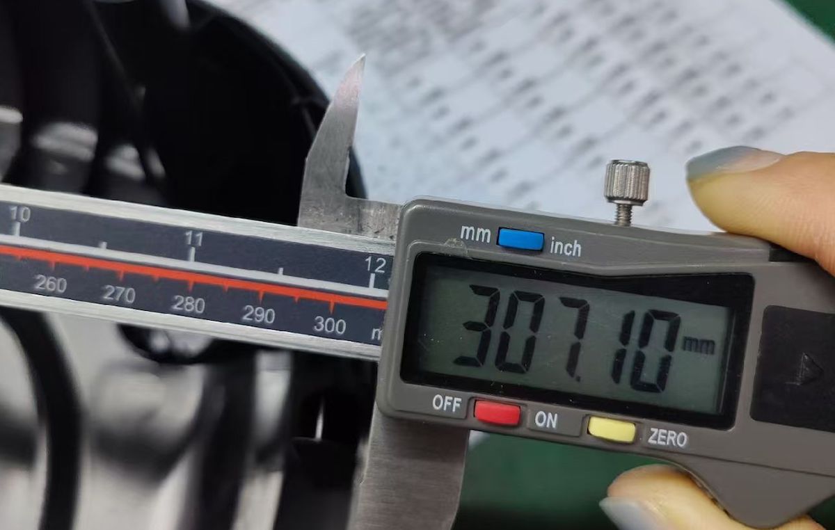
Common inspection equipment includes:
- Calipers.
- Micrometers.
- Height gauges.
- Pin gauges.
- Coordinate Measuring Machines (CMM).
- Optical measurement systems.
CMM inspection is particularly useful for components with complex geometries, multiple hole positions, and critical datum relationships. For production parts, manufacturers should identify critical dimensions and establish an appropriate inspection plan. Inspection frequency and measurement methods should be agreed upon according to product requirements and production risks.
Injection Molding Tolerances: Rapid Tooling vs. Production Tooling
Rapid tooling is commonly used for prototypes, low-volume production, and bridge production, while production tooling is designed for longer production runs and consistent part quality. Both can achieve good dimensional accuracy, but their achievable tolerances depend on mold material, construction, part geometry, plastic shrinkage, and process stability.
Typical Dimensional Tolerances: Rapid Tooling vs. Production Tooling
|
Tooling Type |
Typical Mold Material |
Indicative Part Tolerance* |
|
Rapid tooling |
Aluminum 6061 |
±0.10–0.20 mm |
|
Rapid tooling |
Aluminum 7075 |
±0.05–0.15 mm |
|
Rapid tooling |
P20 steel |
±0.05–0.10 mm |
|
Rapid tooling |
NAK80 steel |
±0.03–0.08 mm |
|
Production tooling |
P20 steel |
±0.05–0.10 mm |
|
Production tooling |
H13 steel |
±0.03–0.08 mm |
|
Production tooling |
S136 steel |
±0.03–0.08 mm |
These are illustrative engineering reference ranges, not guaranteed capabilities oruniversal standards. Actual molded-part tolerances depend on nominal dimensions, material grade, shrinkage, part geometry, mold design, and molding conditions.
Key Factors Affecting Dimensional Accuracy
-
Mold material and wear: Aluminum molds are faster to machine but generally have lower wear resistance than steel molds. P20, H13, and S136 are better suited to longer production runs.
-
Dimensional consistency: Rapid tooling can meet tight tolerances for suitable parts, while production tooling is generally better suited to maintaining consistent dimensions over larger production quantities.
-
Mold construction: Gate location, cooling channels, slides, and interchangeable inserts can affect dimensional stability and repeatability.
-
Material shrinkage: Both tooling approaches must account for plastic shrinkage. Semi-crystalline materials such as nylon, PBT, and POM generally require particular attention.
-
Insert molding: Metal or plastic inserts must be accurately positioned and secured in the mold. Insert movement, thermal expansion, and plastic shrinkage can affect the final dimensions and insert position.
-
Overmolding: When molding one material over another, differences in shrinkage and cooling behavior can cause dimensional variation, warpage, or uneven material coverage. Both materials and molding stages need to be considered.
Rapid Tooling vs. Production Tooling: Which Is Better for Tight Tolerances
Rapid tooling can achieve good dimensional accuracy for prototypes, low-volume production and bridge production when the mold is properly designed and the process is controlled. Production tooling is generally preferred for larger quantities, long-term mold durability, and consistent dimensional performance.
For insert molding and overmolding, tooling accuracy and process control are particularly important because the final dimensions depend on both the substrate or insert and the overmolded material.
At TEAM Rapid, we evaluate part dimensions, plastic materials, insert requirements, tolerance specifications, and production quantities before recommending aluminum or steel tooling. We also inspect molded samples against engineering drawings and make necessary mold or process adjustments before production.
How to Specify Injection Molding Tolerances on Engineering Drawings
Clear tolerance requirements help manufacturers produce consistent injection molded parts and avoid unnecessary tooling costs.
- Identify critical dimensions: Apply tighter tolerances to features that affect assembly, fit, or product function. General dimensions can use wider tolerances.
- Consider material shrinkage: Specify the plastic grade whenever possible, as different materials have different shrinkage rates and dimensional stability.
- Define datums and measurement points: Clearly show reference surfaces, measurement locations, and required inspection methods on the engineering drawing.
- Consider manufacturing capability: Discuss critical tolerances with the mold maker before tooling begins to confirm they are achievable through mold design and injection molding.
Avoid specifying unnecessarily tight tolerances across the entire part. This can increase mold costs, require more process control, and make consistent production more difficult.
Injection Molding Tolerance Considerations at TEAM Rapid
At TEAM Rapid, we consider material properties, part dimensions, mold construction, and molding conditions when evaluating injection molding tolerance requirements.
- Material selection: We consider the shrinkage and dimensional behavior of the specified plastic, including differences between amorphous and semi-crystalline materials.
- Mold manufacturing: Mold dimensions and steel selection are planned according to the required part dimensions and expected material shrinkage.
- Molding process: Injection pressure, temperature, holding time, and cooling conditions are controlled to help maintain dimensional consistency.
- Sample inspection: We check molded samples against the drawing requirements and make necessary mold or process adjustments before production.
Whether you need prototype parts, low-volume production, or larger quantities, TEAM Rapid can review your drawings and manufacturing requirements to assess achievable tolerances before tooling begins.
Frequently Asked Questions About Injection Molding Tolerances
Q: What Is the Typical Tolerance for Injection Molded Plastic Parts?
A: There is no single tolerance that applies to all injection molded plastic parts.
Achievable tolerances depend on the material, part size, geometry, mold design, processing conditions, and inspection requirements.
Small components made from dimensionally stable materials may achieve tighter tolerances than large components with complex geometries.
Engineers should specify tolerances according to functional requirements and discuss critical dimensions with the manufacturer before tooling begins.
Q: Which Plastic Materials Have the Best Dimensional Stability?
A: Amorphous materials such as ABS and PC generally have relatively low and predictable molding shrinkage.
However, the actual dimensional stability depends on the resin grade, component design, processing conditions, and operating environment.
Some reinforced semi-crystalline materials can also provide good dimensional stability when properly designed and processed.
Material selection should consider the complete application rather than shrinkage alone.
Q: Are Injection Molding Tolerances Tighter for ABS or Nylon?
A: ABS generally offers more predictable molding shrinkage and is less sensitive to moisture absorption than nylon.
Nylon can experience greater dimensional changes because of crystallization during cooling and moisture absorption after molding.
However, the final achievable tolerance depends on the specific material grade, part geometry, mold design, and processing conditions.
For precision applications, both materials require proper mold design and dimensional verification.
Q: Why Are Nylon Injection Molded Parts Difficult to Hold to Tight Tolerances?
A: Nylon is a moisture-absorbing semi-crystalline plastic.
Its dimensions can change during cooling, crystallization, and subsequent moisture conditioning.
Glass-fiber reinforcement can also create directional shrinkage because fibers tend to align with material flow.
These factors make nylon dimensional control more challenging, especially for components with tight hole positions, mating dimensions, and assembly requirements.
Q: How Does Glass Fiber Affect Injection Molding Tolerances?
A: Glass-fiber reinforcement generally reduces overall molding shrinkage and improves stiffness.
However, glass fibers tend to align with material flow during injection molding.
This can cause different shrinkage rates in the flow and cross-flow directions, resulting in anisotropic shrinkage and potential warpage.
Therefore, gate location, part geometry, fiber content, and mold design should all be considered when molding glass-fiber-reinforced plastics.
Q: Can Injection Molded Plastic Parts Achieve ±0.05 mm Tolerances?
A: Yes, ±0.05 mm may be achievable for selected dimensions in certain injection molded components.
However, it should not be considered a standard tolerance for every plastic part.
Achieving this level of accuracy depends on factors such as:
- Part size and geometry.
- Material shrinkage and dimensional stability.
- Mold precision.
- Processing consistency.
- Inspection method and environmental conditions.
A small, well-supported component made from a suitable material may achieve tighter tolerances than a large, thin-walled component.
The manufacturer should evaluate critical dimensions before confirming the achievable tolerance.



 Contact