
Injection Molding Wall Thickness Design Guidelines: How to Design Smooth Transitions
Wall thickness is a critical factor in injection molded part design. Improper wall thickness can cause sink marks, voids, warpage, differential shrinkage, and incomplete filling. These defects affect part appearance, dimensional accuracy, and production efficiency.Following injection molding wall thickness design guidelines to using smooth, gradual thickness transitions can reduce these defects.
Proper injection molding wall thickness design guidelines helps engineers achieve consistent plastic flow, cooling, and shrinkage. In this article, we explore recommended wall thicknesses, transition design principles, common design mistakes, and ways to optimize plastic parts for standard injection molding, rapid tooling, and low-volume production.
Why Wall Thickness Design Matters in Injection Molding
Wall thickness affects plastic flow, cooling time, part strength, dimensional accuracy, and molding costs. Maintaining consistent thickness helps produce higher-quality parts with fewer defects.
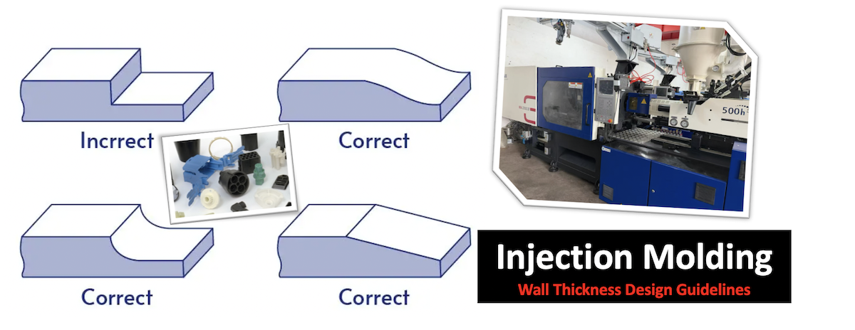
How Wall Thickness Affects Plastic Flow and Cooling
Molten plastic flows differently through thick and thin sections. Thin walls create greater flow resistance, while thick sections contain more material and generally require longer cooling times.
When thickness varies significantly, different areas cool and solidify at different rates, increasing shrinkage and dimensional variation.
Common Defects Caused by Uneven Wall Thickness
Uneven wall thickness can contribute to several molding defects:
- Sink marks:Thick sections shrink and create surface depressions.
- Voids:Internal cavities form when thick sections shrink during cooling.
- Warpage:Uneven cooling and shrinkage deform the molded part.
- Differential shrinkage:Different sections shrink at different rates.
- Incomplete filling:Thin sections may restrict plastic flow and cause short shots.
The Relationship Between Wall Thickness and Injection Molding Cost
Thick sections consume more plastic and require longer cooling times. This increases material costs, extends molding cycles, and reduces machine productivity. Optimizing wall thickness helps reduce unnecessary material usage and improve production efficiency.
Injection Molding Wall Thickness Design Guidelines
Good wall thickness design starts with maintaining a consistent nominal thickness while considering material properties, part geometry, and structural requirements.
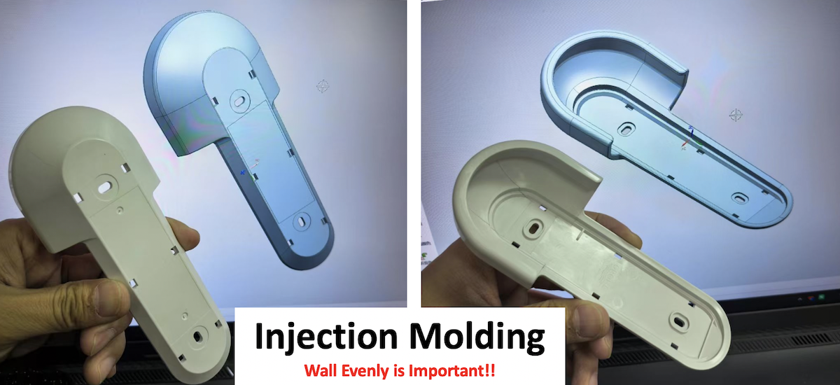
Maintain Uniform Wall Thickness Whenever Possible
Uniform wall thickness helps molten plastic flow and cool consistently, reducing sink marks, voids, and warpage.
- For example, a plastic housing with a consistent 2 mm wall is generally easier to mold than one with alternating 2 mm and 5 mm sections.
When thickness variations are necessary, use gradual transitions and avoid excessive material accumulation.
Recommended Wall Thickness for Common Injection Molding Materials
Different plastics have different flow characteristics and mechanical properties. The following table provides typical starting ranges for common plastic injection molding materials.
|
Plastic Material |
Typical Wall Thickness |
|
ABS |
3.0–3.5mm |
|
PC |
3.0–3.5mm |
|
PP |
0.8–3.5 mm |
|
PA (Nylon) |
0.8–3.0 mm |
|
POM |
0.8–3.0 mm |
|
PMMA |
3.0–3.5mm |
|
PE |
0.8–3.5 mm |
|
PBT |
1.0–3.5 mm |
|
PEEK |
1.0–3.0 mm |
|
|
|
These are general reference ranges. Actual recommendations depend on material grade, part geometry, flow length, gate location, and molding conditions. For many conventional plastic housings and mechanical components, 1.5–3.0 mm is a practical starting range.
Consider Part Strength Instead of Simply Increasing Wall Thickness
Increasing wall thickness does not always provide the most efficient way to improve strength.
Instead, engineers can use:
- Ribs:Improve stiffness without thickening the main wall.
- Gussets:Reinforce corners and mounting areas.
- Cored bosses:Reduce material buildup while maintaining mounting strength.
For example, adding ribs to a 2 mm housing wall may provide sufficient stiffness without increasing the entire wall to 4 mm. You can refer to ribs and bosses design guidelines.
Follow Practical Wall Thickness Tolerances
Achievable wall thickness consistency depends on material shrinkage, part dimensions, mold machining accuracy, and molding conditions.
Engineers should define appropriate dimensional tolerances based on the part's function and assembly requirements.
A manufacturer DFM review can identify areas where thickness consistency may be difficult to achieve and recommend practical improvements before tooling begins.
How to Design Wall Thickness Transitions for Injection Molding
Different wall thicknesses are sometimes necessary, but abrupt changes can create uneven cooling, differential shrinkage, and localized stress. The goal is to connect different sections smoothly without creating unnecessary material accumulation.
Avoid Sudden Wall Thickness Changes
- A sudden change from a 2 mm wall to a 5 mm section creates a localized thick area.
- The thicker section cools more slowly and may develop sink marks, voids, or warpage.
- Avoid sharp steps and sudden changes wherever possible.
Use Gradual Tapered Transitions
A tapered transition gradually connects thin and thick sections.
- For example, instead of connecting a 2 mm wall directly to a 4 mm section, introduce an inclined surface that progressively increases the thickness.
A longer, gradual transition generally provides better cooling and shrinkage behavior than an abrupt step.
Apply Radii and Fillets at Wall Thickness Transitions
Sharp corners can create stress concentrations and abrupt geometry changes. Adding suitable radii and fillets helps create smoother connections, improve part strength, and reduce localized material buildup. However, avoid oversized fillets that create unnecessarily thick sections.
Recommended Wall Thickness Transition Ratios
As a practical starting guideline, engineers should aim to keep adjacent wall thicknesses within approximately a 1.5:1 ratio wherever possible.
For example:
- 2 mm to 2.5 mm: Generally a manageable thickness change.
- 2 mm to 3 mm: May be acceptable with a gradual transition.
- 2 mm to 5 mm: Requires more careful redesign and evaluation.
These are general guidelines rather than strict limits. Material properties, geometry, and molding conditions determine the final acceptable transition.
Design Wall Thickness Transitions Around Ribs, Bosses, and Corners
Ribs, bosses, and corners are common locations for excessive material accumulation.
Consider these recommendations:
- Ribs:Start with approximately 50–60% of the nominal wall thickness.
- Bosses:Use cored designs and supporting ribs instead of solid thick sections.
- Corners:Apply suitable radii and avoid excessive material at intersections.
These modifications help maintain more consistent cooling and reduce sink mark risks.
Wall Thickness Transitions in Insert Molding
In insert molding, metal or plastic inserts are placed inside the mold before molten plastic is injected around them. The transition between the insert and surrounding plastic requires careful design to avoid excessive material buildup and uneven cooling.
Engineers should consider:
- Maintain consistent plastic thickness around the insert wherever possible.
- Avoid excessively thick plastic sections at the insert base.
- Use suitable radii and gradual transitions around insert edges.
- Provide sufficient plastic coverage and mechanical retention.
- Consider the insert's thermal conductivity, as metal inserts can affect local cooling behavior.
For example, a brass threaded insert in a plastic housing needs sufficient surrounding material for retention without creating an unnecessarily thick section that may cause sink marks or warpage.
Wall Thickness Transitions in Overmolding
Overmolding combines two materials, such as a rigid plastic substrate and a softer TPE or TPU layer. Wall thickness design is important for achieving consistent material coverage, good bonding, and reliable part quality.
Engineers should consider:
- Maintain consistent overmold thickness wherever practical.
- Avoid sudden changes in the thickness of the overmolded layer.
- Use gradual transitions around edges and corners.
- Ensure sufficient substrate support beneath the softer material.
- Consider material compatibility and differences in shrinkage.
For example, when overmolding a TPE grip onto a rigid ABS handle, consistent TPE thickness helps improve material coverage and appearance. Abrupt thickness changes may cause uneven cooling, inconsistent shrinkage, and surface defects.
The substrate and overmold materials should also be evaluated for compatibility and processing temperature requirements before finalizing the design.
How to Prevent Injection Molding Warpage Caused by Wall Thickness Variations
Warpage occurs when different areas of a molded part shrink unevenly during cooling. Wall thickness variations are one of the factors that contribute to this problem.
How Uneven Wall Thickness Causes Warpage
Thick sections generally cool more slowly than thin sections. Their different cooling and shrinkage behavior can create internal stresses. These stresses may cause the part to bend, twist, or deform after ejection. Maintaining consistent wall thickness helps reduce this risk.
Avoid Thick Sections at Wall Intersections
When multiple walls meet, they can create locally thick sections.
- These areas may cool slowly and develop sink marks, voids, and warpage.
- Reduce overlapping material, use cored geometry, and introduce ribs or gussets where structural support is required.
Use Ribs Instead of Solid Thick Sections
Ribs improve stiffness without unnecessarily increasing the main wall thickness.
- As a starting point, rib thickness is often designed at 50–60% of the nominal wall thickness. Suitable rib height, spacing, and draft should also be considered.
This approach helps reduce material buildup while maintaining structural performance.
Optimize Cooling and Mold Design
Good mold cooling is essential for dimensional stability.
Engineers should consider:
- Cooling channel placement and spacing.
- Uniform mold temperature.
- Cooling efficiency around thick sections.
- Appropriate cooling time.
- Material-specific processing conditions.
For complex parts, mold flow analysis can help identify cooling problems and evaluate potential warpage.
Wall Thickness Transition Design Examples: Good vs. Bad
Practical examples help engineers understand how geometry changes affect injection molding quality.
Abrupt Thickness Transition vs. Gradual Transition
Bad design: A 2 mm wall suddenly increases to 5 mm, creating a thick area that cools more slowly.
Good design: A gradual taper connects the two sections, reducing sudden geometry changes and improving cooling consistency.
Solid Boss vs. Properly Cored Boss Design
Bad design: A solid boss creates excessive material around its base, increasing sink mark and cooling risks.
Good design: A cored boss removes unnecessary material and uses supporting ribs to maintain strength.
Thick Wall Intersection vs. Rib-Supported Design
Bad design: Multiple solid walls overlap, creating a thick intersection.
Good design: Reduce overlapping material and use ribs to provide structural support without excessive thickness.
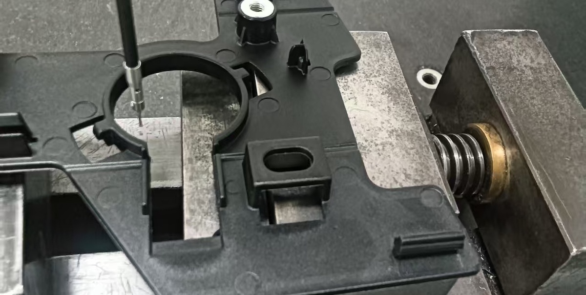
Before and After: Improving a Plastic Part's Wall Thickness Design
Consider a plastic electronic enclosure with a 2 mm nominal wall.
A DFM review identifies several problems:
- Solid mounting bosses.
- Thick internal wall intersections.
- An abrupt transition from 2 mm to 4.5 mm.
- Oversized ribs that may cause exterior sink marks.
The recommended improvements include cored bosses, thinner ribs, gradual transitions, and reduced material at intersections. These changes create more consistent wall thickness and can reduce cooling, shrinkage, and warpage risks.
How to Evaluate Wall Thickness During Injection Molding DFM
Wall thickness should be reviewed before mold manufacturing. CAD analysis, mold flow simulation, and manufacturer DFM reviews help identify potential problems early.
Use CAD Analysis to Identify Wall Thickness Variations
3D CAD software provides wall thickness analysis tools that help identify:
- Excessively thick sections.
- Unnecessarily thin areas.
- Abrupt thickness changes.
- Thick intersections.
- Material buildup around bosses and ribs.
Color-coded thickness maps make it easier for engineers to locate areas requiring design improvements.
Use Mold Flow Analysis to Evaluate Wall Thickness Design
Mold flow analysis helps engineers evaluate how wall thickness variations affect plastic flow, filling pressure, cooling, and shrinkage. By simulating the injection molding process, engineers can identify potential problems such as short shots, air traps, uneven cooling, sink marks, and warpage.
- For example, simulation can help determine whether a thick mounting area creates a hot spot or whether a thin section restricts plastic flow. Engineers can then optimize wall thickness, gate locations, and cooling channel layouts before mold manufacturing.
Review Wall Thickness During the Design for Manufacturability (DFM) Process
A DFM review evaluates whether a plastic part can be manufactured reliably and economically.
Engineers typically check nominal wall thickness, transitions, ribs, bosses, corners, plastic flow, and cooling requirements. Identifying these problems before tooling begins helps reduce mold modifications, production delays, and quality risks.
How TEAM Rapid Helps Optimize Injection Molded Part Designs
At TEAM Rapid, our engineering team provides DFM reviews to help customers improve plastic part manufacturability. We evaluate wall thickness, structural features, transitions, draft angles, and other important design details before mold manufacturing.
Our capabilities include:
- Plastic part DFM review.
- Custom injection mold design and manufacturing.
- Rapid tooling for prototypes and low-volume production.
- Bridge tooling.
- Low-volume and high-volume injection molding.
We help customers optimize part designs for reliable molding, shorter tooling lead times, and consistent production quality. Visit TEAM Rapid to learn more about our injection molding and rapid tooling services.
Wall Thickness Design Considerations for Rapid Tooling and Low-Volume Production
The fundamental wall thickness design principles remain the same for standard injection molding, rapid tooling, and low-volume production. However, tooling materials, mold structures, production quantities, and cost considerations can influence design decisions.
Wall Thickness Guidelines for Rapid Tooling
Rapid tooling focuses on shorter mold manufacturing lead times and lower tooling costs. Aluminum alloys such as 7075 may be used when the expected production volume and molding conditions allow. P20 steel can be selected when greater wear resistance and tool life are required.
Different mold materials have different thermal properties, which influence cooling behavior. Engineers should consider these differences when evaluating thick sections and wall thickness transitions.
Wall Thickness Design for Low-Volume Injection Molding
Low-volume injection molding generally follows the same wall thickness guidelines as standard production. However, manufacturers may prioritize simpler mold structures and economical tooling solutions.
- For example, manual inserts or interchangeable mold inserts can sometimes replace complex automated mechanisms. Regardless of tooling structure, engineers should maintain consistent wall thickness and avoid excessive material accumulation to reduce sink marks and warpage.
Wall Thickness Considerations for Bridge Production
Bridge production provides a manufacturing solution between prototyping and mass production.
Part designs may need to balance functional requirements, tooling investment, lead time, and production quantity.
Although some design compromises may be acceptable, engineers should not ignore wall thickness transitions, cooling behavior, or shrinkage risks.
A DFM review helps determine whether the existing design is suitable for rapid tooling and bridge production or requires modifications before mold manufacturing.
Final Design Checklist for Injection Molding Wall Thickness
Before releasing a plastic part design for tooling, check the following:
- Maintain consistent wall thickness wherever practical.
- Avoid abrupt thickness changes.
- Use gradual tapers and rounded transitions.
- Core out unnecessarily thick sections.
- Use ribs and gussets to improve structural strength.
- Avoid material accumulation at intersections.
- Check cooling and shrinkage risks.
- Consider insert molding and overmolding requirements where applicable.
- Perform DFM and mold flow analysis for complex parts.
Frequently Asked Questions About Injection Molding Wall Thickness
Q: What Is the Recommended Wall Thickness for Injection Molding?
A: For many conventional plastic parts, 1.5–3.0 mm is a practical starting range. The final thickness depends on material properties, part geometry, structural requirements, and molding conditions.
Q: Why Should Wall Thickness Be Uniform in Injection Molding?
A: Uniform wall thickness helps plastic flow, cool, and shrink more consistently. It reduces the risks of sink marks, voids, warpage, and dimensional variations.
Q: How Do You Design a Wall Thickness Transition in Injection Molding?
A: Use gradual tapers, suitable radii, and fillets to connect different wall sections. Avoid sudden thickness changes and excessive material buildup.
Q: How Does Wall Thickness Affect Injection Molding Warpage?
A: Different wall thicknesses create different cooling and shrinkage rates. These differences can generate internal stresses and cause the molded part to bend or twist.
Q: Can Different Wall Thicknesses Be Used in One Injection Molded Part?
A: Yes. Different thicknesses are acceptable when required for structural or functional reasons. However, gradual transitions and proper material distribution are important for reliable molding.
Q: How Can Thick Sections Be Reduced Without Sacrificing Part Strength?
A: Use ribs, gussets, cored bosses, and optimized structural geometry instead of simply increasing wall thickness.
Q: Does Wall Thickness Affect Injection Molding Cycle Time?
A: Yes. Thick sections generally require longer cooling times, increasing the molding cycle. Optimizing wall thickness helps improve cooling efficiency and production output.



 Contact