
Injection Molding for Smart Home Products: Materials & Challenges
Injection molding for smart home products involves selecting appropriate engineering plastics (such as ABS, PC/ABS, PP, or PA), integrating electronics within tight enclosures, managing heat and EMI, maintaining dimensional accuracy and cosmetic quality, and addressing common defects like warpage, sink marks, and weld lines—all while balancing tooling strategy and production volume to achieve cost-effective, high-quality manufacturing. Whether you are designing a smart thermostat housing, Wi-Fi camera enclosure, or voice assistant shell, the interaction between material selection, DFM, and tooling can have a major impact on the final result.

This guide covers the practical considerations mechanical engineers, product designers, and purchasing teams need to address when taking smart home injection molded parts from concept to production.
Injection Molding Home Products: From Design to Production
A practical workflow takes a smart home component from CAD data through tooling, validation, and production. Each step affects the next, so skipping an early review can lead to mold rework, redesigns, or launch delays.
Step 1 — Product and DFM Review
Review the part geometry, material, tolerances, assembly requirements, cosmetic specifications, and expected production volume. This is where many design-for-manufacturability issues are identified.
Smart home enclosures often combine thin walls with bosses, snap fits, and openings for connectors or antennas. Consistent wall thickness is important for controlling sink marks and warpage. Draft angles of 1° to 2° per side are standard, although textured surfaces may require additional draft(1.5° of draft for every 0.025 mm (0.001 in) of texture depth).
At this stage, confirm whether the part will contain a PCB, battery, or antenna module. These internal components can affect wall thickness, rib placement, and fastener selection. Getting DFM feedback early can prevent weeks of redesign later.
Step 2 — Mold Design and Tooling
Finalize the mold structure, gating, cooling, ejection, steel selection, and other tooling details. For smart home products, gate location has a direct effect on cosmetic appearance and the location of weld lines on visible surfaces.
Submarine gates or edge gates are common choices for enclosures where the gate vest needs to remain hidden. Cooling channels should be laid out to account for changes in wall thickness, particularly around thick bosses or rib intersections. Ejection also needs to be balanced to prevent distortion in thin-walled sections.
When evaluating tooling options, determine whether you need prototype tooling for design validation, bridge tooling for pilot runs, or hardened production tooling for full-scale manufacturing. Rapid Tooling Services from TEAM Rapid can help match the tooling strategy to your project timeline and production volume.
Step 3 — T1 Sampling and Mold Validation
Initial samples are inspected for dimensional, cosmetic, material, and functional issues before production approval. T1 samples are the first parts produced from the actual mold cavity.
During T1 evaluation, check critical dimensions against the engineering drawing. Verify snap-fit engagement force, surface finish, and assembly interfaces. If the part houses electronics, make sure the internal clearances provide enough room for the PCB and connectors without interference.
Document the findings and agree on acceptable deviations before authorizing mold corrections. A structured T1 report also keeps communication clear between the design team and mold maker.
Summary Table
Step 4 for product or mold modifications if need.
Step
Key Activities
Important Considerations
Best Practices / Tips
Step 1 — Product and DFM Review
Review part geometry, material, tolerances, assembly requirements, cosmetic specs, and expected production volume
• Thin walls combined with bosses, snap fits, and connector/antenna openings are common in smart home enclosures
• Confirm early if the part houses a PCB, battery, or antenna module
Step 2 — Mold Design and Tooling
Finalize mold structure, gating, cooling, ejection, steel selection, and tooling details
• Gate location directly affects cosmetic appearance and weld line placement
• Choose tooling type based on project stage:
Step 3 — T1 Sampling and Mold Validation
Inspect initial samples for dimensional, cosmetic, material, and functional issues before production approval
• T1 samples are the first parts from the actual mold cavity
• Document all findings in a structured T1 report
Step 4 — Verification and Mold Correction
Implement mold modifications based on T1 findings, produce T2/T3 samples, and conduct final verification before production release
• Mold corrections may include adjusting gate size, modifying cooling channels, polishing surfaces, or re-machining cavity dimensions
• Limit revision cycles by addressing all T1 issues in a single correction round where possible
• Consistent wall thickness controls sink marks and warpage
• Draft angles: 1°–2° per side (add 1.5° per 0.025 mm texture depth)
• Internal components affect wall thickness, rib placement, and fastener selection
• Get DFM feedback early to avoid weeks of redesign
• Submarine or edge gates hide gate vest on visible surfaces
• Cooling channels must account for wall thickness variations (thick bosses, rib intersections)
• Balanced ejection prevents distortion in thin-walled sections
– Prototype tooling → design validation
– Bridge tooling → pilot runs
– Hardened production tooling → full-scale manufacturing
• TEAM Rapid's Rapid Tooling Services can match tooling strategy to timeline and volume
• Check critical dimensions against engineering drawings
• Verify snap-fit engagement force, surface finish, and assembly interfaces
• Confirm internal clearances for PCB and connectors
• Agree on acceptable deviations before authorizing mold corrections
• Clear T1 reporting keeps communication aligned between design team and mold maker
• Each revision cycle (T2, T3) should be tracked with updated inspection reports
• Functional testing with actual electronics (PCB, connectors, antennas) confirms real-world fit
• Use CMM or opt
Mold Material and Expected Production Volume
Tool steel and mold construction should be selected based on production volume, material characteristics, tolerances, and expected tool life.
- For low-volume runs or bridge production, pre-hardened steels such as P20 or 718H provide a good balance of machinability and durability.
- For high-volume smart home products exceeding 500,000 cycles, hardened tool steels such as H13 or S136 offer better wear resistance, particularly when processing abrasive or corrosive resins.
If the material contains glass fiber or flame-retardant additives, specify the appropriate steel hardness. Surface treatments such as nitriding or DLC coating can also help extend mold life. Corrosion-resistant steels are recommended when processing PVC-based or halogenated flame-retardant compounds.
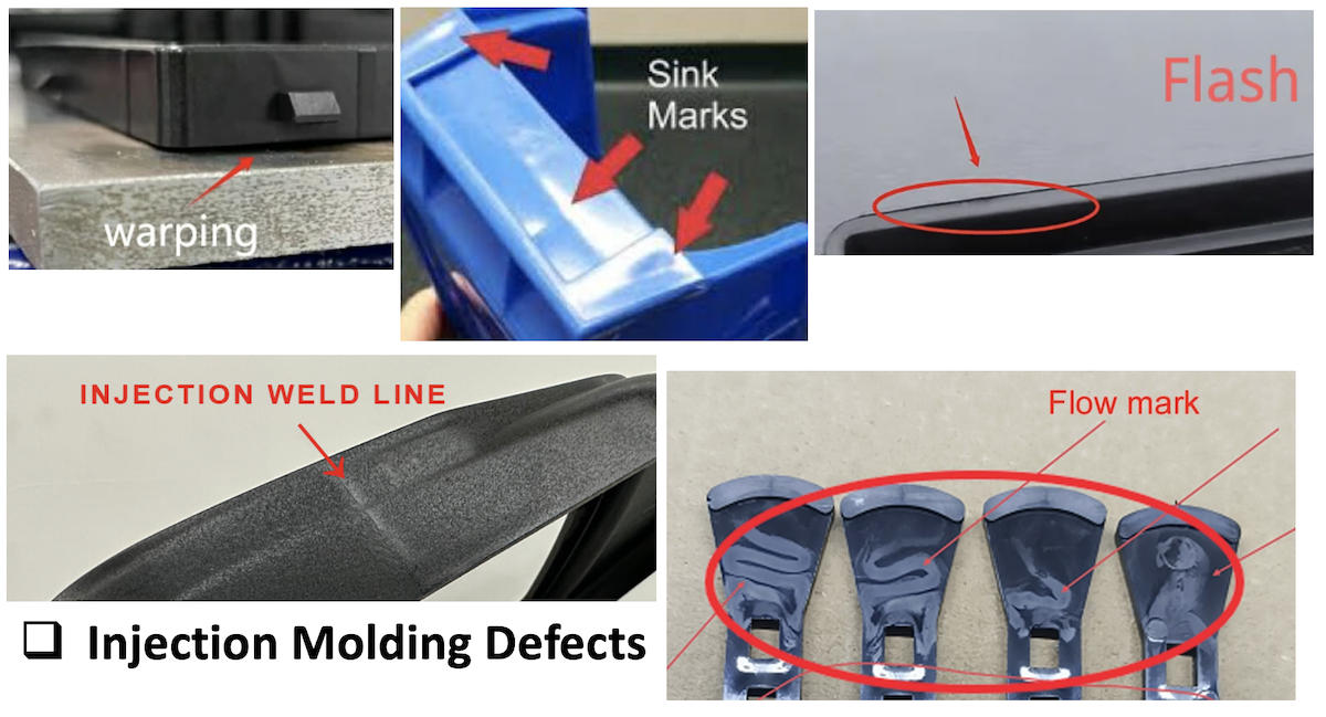
Common Injection Molding Problems in Smart Home Products
Understanding common defects helps engineering and purchasing teams identify potential root causes before production issues become costly. Smart home enclosures are especially sensitive to cosmetic and dimensional problems because many of these parts are directly visible to the end user.
Warpage and Shrinkage
Uneven cooling, material behavior, wall thickness, and molding conditions can all contribute to dimensional distortion. Smart home housings with large flat surfaces are particularly prone to warpage.
Semi-crystalline materials such as PA66 or POM have higher anisotropic shrinkage rates than amorphous resins such as ABS or PC. If the design requires tight flatness tolerances, consider an amorphous material or add ribbing to increase stiffness without increasing wall thickness.
Mold temperature uniformity is another common root cause. Make sure cooling channels are balanced and that the mold temperature controller maintains consistent conditions throughout the cavity.
Sink Marks
Sink marks appear on surfaces opposite thick features such as bosses, ribs, or screw posts. On Class A surfaces of smart home products, they are generally unacceptable.
Reduce rib thickness to 40–50% of the adjacent wall thickness. Where possible, use coring or gussets instead of solid bosses. Packing pressure and hold time can be adjusted to compensate, but geometry changes are generally more reliable than process adjustments alone.
Weld Lines and Flow Marks
Weld lines form where separate melt fronts meet. They commonly appear around openings for buttons, ports, or antenna windows. Besides creating visible cosmetic defects, weld lines can reduce local part strength.
Gate location, melt temperature, and mold temperature all affect weld line strength and visibility. For smart home products with demanding cosmetic requirements, position gates so weld lines occur on non-visible surfaces or are hidden by assembly features.
Flash and Parting Line Issues
Flash occurs when molten plastic escapes through the parting line or ejector pin clearances. On smart home enclosures with tight parting-line requirements, even a small amount of flash can interfere with assembly or leave sharp edges.
Check mold shut-off surfaces during T1 inspection. If flash continues, verify clamp force, mold flatness, and whether the injection pressure is higher than the mold can contain.
Quality Control for Injection Molding Products
Smart home components need consistent dimensions, appearance, material properties, and assembly interfaces throughout production. A structured quality control plan helps prevent batch-to-batch variation from reaching the customer.
Dimensional Inspection
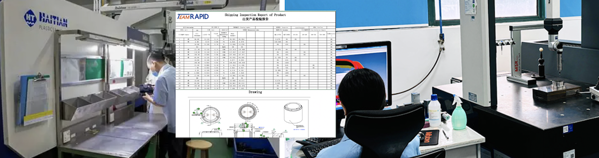
Critical dimensions should be measured against the engineering drawings and agreed tolerances using appropriate inspection equipment. For smart home enclosures, this typically includes overall length, width, height, boss positions, and snap-fit feature dimensions.
CMM measurement is recommended for first-article inspection and periodic audits. In high-volume production, functional gauges or go/no-go fixtures can speed up inline inspection while maintaining accuracy for critical features.
Define which dimensions are critical, major, or minor. This gives the quality team a clear basis for setting inspection frequency and responding when measurements begin to move toward tolerance limits.
Material and Color Verification
Material grades, certificates, color requirements, and cosmetic standards should be verified before and during production. Smart home products often specify exact resin grades with specific UL ratings, impact modifiers, or UV stabilizers.
Request material certificates of compliance (COC) for each resin lot. For colored parts, use a spectrophotometer to measure color difference (ΔE) against an approved standard. A ΔE threshold of 1.0 or less is typical for consumer-visible smart home components.
If the product uses overmolding or insert molding, verify adhesion between the materials through peel testing or cross-hatch tape tests at defined intervals.
First Article and Production Inspection
First-article inspection confirms whether the mold and process meet the requirements before larger production quantities are released. The inspection should cover critical dimensions, cosmetic appearance, material verification, and functional testing.
During ongoing production, implement a sampling plan based on AQL standards. Common practice for smart home components is AQL 0.65 for critical defects, 1.0 for major defects, and 2.5 for minor defects.
Track process parameters such as injection pressure, melt temperature, mold temperature, and cycle time. Statistical process control (SPC) charts can help identify trends before they result in out-of-spec parts.
Conclusion: Designing Smarter for Injection Molding
Successful smart home injection molding starts with material selection and DFM decisions that account for electronics, assembly, appearance, tolerances, tooling, and production volume. These factors are closely connected. Addressing them early in the design phase can reduce iteration cycles and overall project cost.
For engineering and purchasing teams evaluating injection molding for smart home products, the supplier needs to understand both the design intent and the manufacturing constraints. Clear communication during DFM review, structured T1 validation, and consistent quality control throughout production can make the difference between a smooth launch and costly rework.
If you are ready to move your smart home product from design to production, TEAM Rapid offers Plastic Injection Molding Services covering DFM analysis, rapid tooling, T1 sampling, and full production runs. Visit TEAM Rapid to upload your CAD files and receive a detailed DFM report with a competitive quote within 24 hours.


 Contact